22 SD Series Technical Manual MDS 05-4846A01, Rev. D
COM1 (Serial) Connection
The default factor settings for the radio’s COM1 port (Figure 17) assigns
it for management or diagnostics of the radio via a serial connection to
a PC. COM1 may be used to set basic parameters such as output power,
modem type and operating frequency of the radio.
This method provides an alternative to the web-based SD Device Man-
ager, accessible via the Ethernet RJ-45 port (see Page 20) when Ethernet
connectivity is not available. If you wish to use serial or Telnet control
instead, refer to the SD Serial/Telnet Management Supplement, Part No.
05-6193A01.
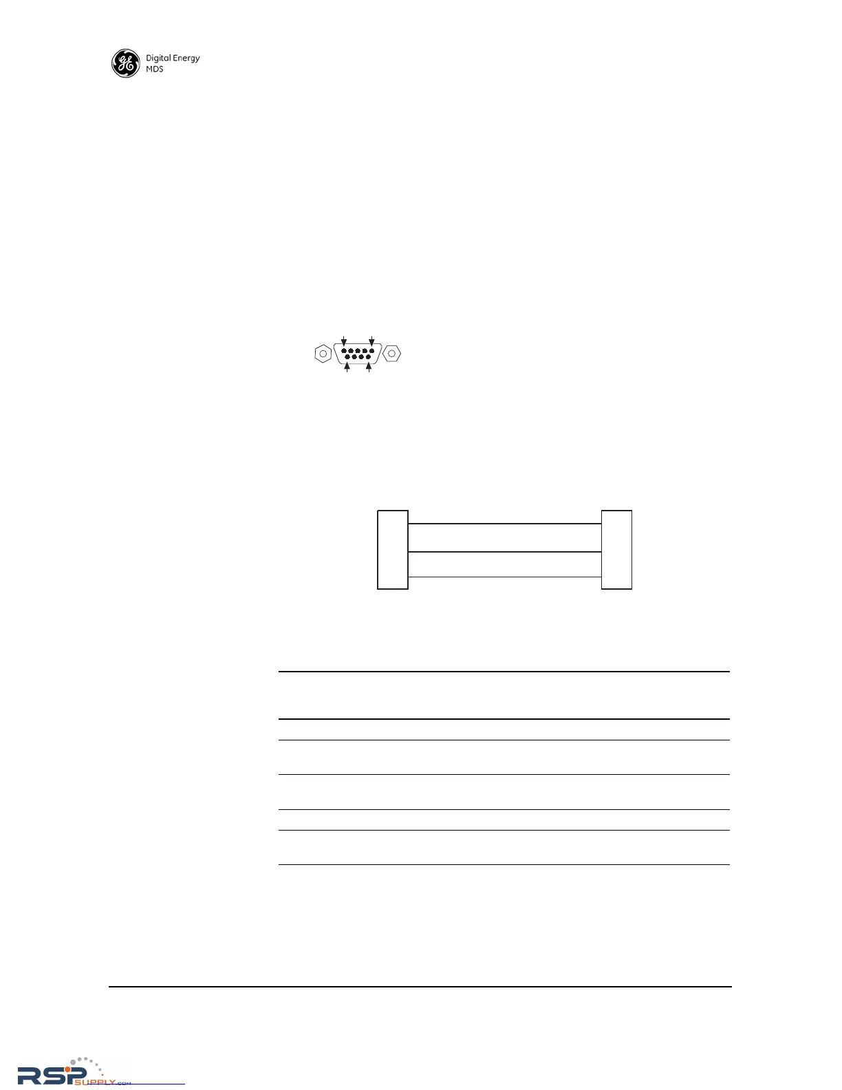
For typical applications, a straight-through DB-9 cable may be used for
PC management. If desired, a cable may be constructed as shown in
Figure 18, using Pins 2 (RXD), 3 (TXD), and 5 (Ground). Table 7 lists
all COM1 pins.
Figure 18. COM1 Wiring for PC Management
Figure 17. COM1 Connector (DB-9F)
As viewed from outside the unit
Table 7. COM1 Pin Descriptions
Pin
Number
Radio
Input/
Output
Pin Description
1 -- No function
2OUTRXD (Received Data)—Supplies received data to the
connected device.
3INTXD (Transmitted Data)—Accepts TX data from the
connected device.
4 -- No function
5--Ground—Connects to ground (negative supply potential) on
chassis.