MDS 05-4846A01, Rev. D SD Series Technical Manual 23
COM2 (Data) Connections
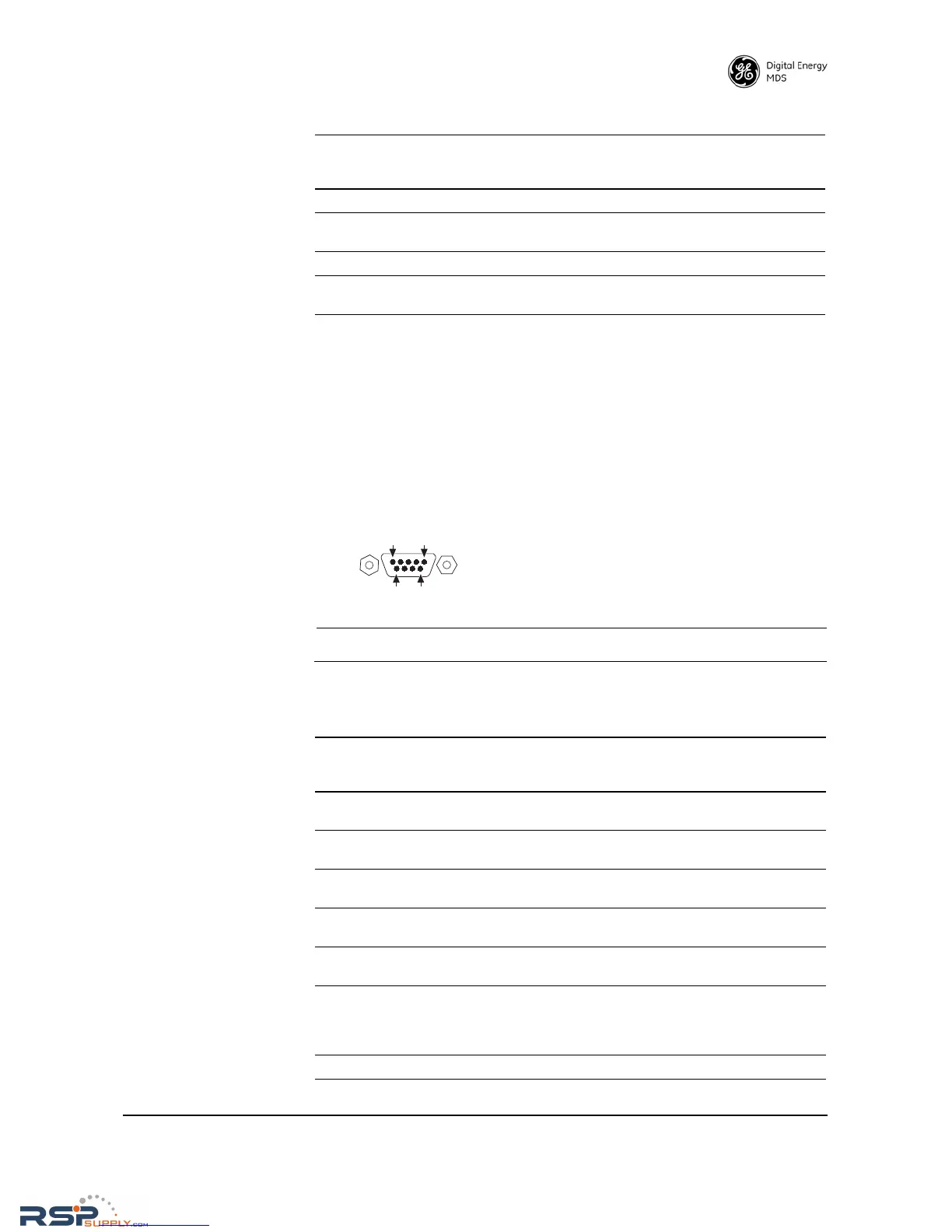
Typically, the COM2 port (Figure 19) is used for connecting the radio to
an external DTE serial device supporting the RS-232 or RS-485 serial
data format. The radio supports serial data rates of 300, 1200, 2400,
4800, 9600, 19200, and 38400, 57600, 115200 bps (asynchronous only).
Pin Descriptions—
RS-232 and
RS-422/485 Mode
Table 8 and Table 9 provide detailed pin descriptions for the COM2 data
port in RS-232 mode and RS-422/485 modes, respectively.
NOTE: The radio is hard-wired as a DCE device.
6 -- No function
7 -- No function in most applications—User I/O for special
applications
8 --- No function
9 -- No function in most applications—User I/O for special
applications
Table 7. COM1 Pin Descriptions
Pin
Number
Radio
Input/
Output
Pin Description
Figure 19. COM2 Connector (DB-9F)
As viewed from outside the radio
Table 8. COM2 Pin Descriptions—Radio in RS-232 Mode
Pin
Number
Radio
Input/
Output
Pin Description
1OUTDCD (Data Carrier Detect/Link)—A low indicates signal
received.
2OUTRXD (Received Data)—Supplies received data to the
connected device.
3INTXD (Transmitted Data)—Accepts TX data from the
connected device.
4INSleep Mode Input—Grounding this pin places the radio in a
low power consumption mode.
5--Signal Ground—Connects to ground (negative supply
potential) on chassis.
6OUTAlarm Output (DSR)—Behavior is user-configurable. Default
behavior: An RS-232 high/space (+5.0 Vdc) on this pin
indicates an alarm condition. An RS-232 low/mark (–5.0 Vdc)
indicates normal operation.
7INRTS (Request-to-Send)—Keys the transmitter.