24 SD Series Technical Manual MDS 05-4846A01, Rev. D
COM2 PORT NOTES & WIRING ARRANGEMENTS:
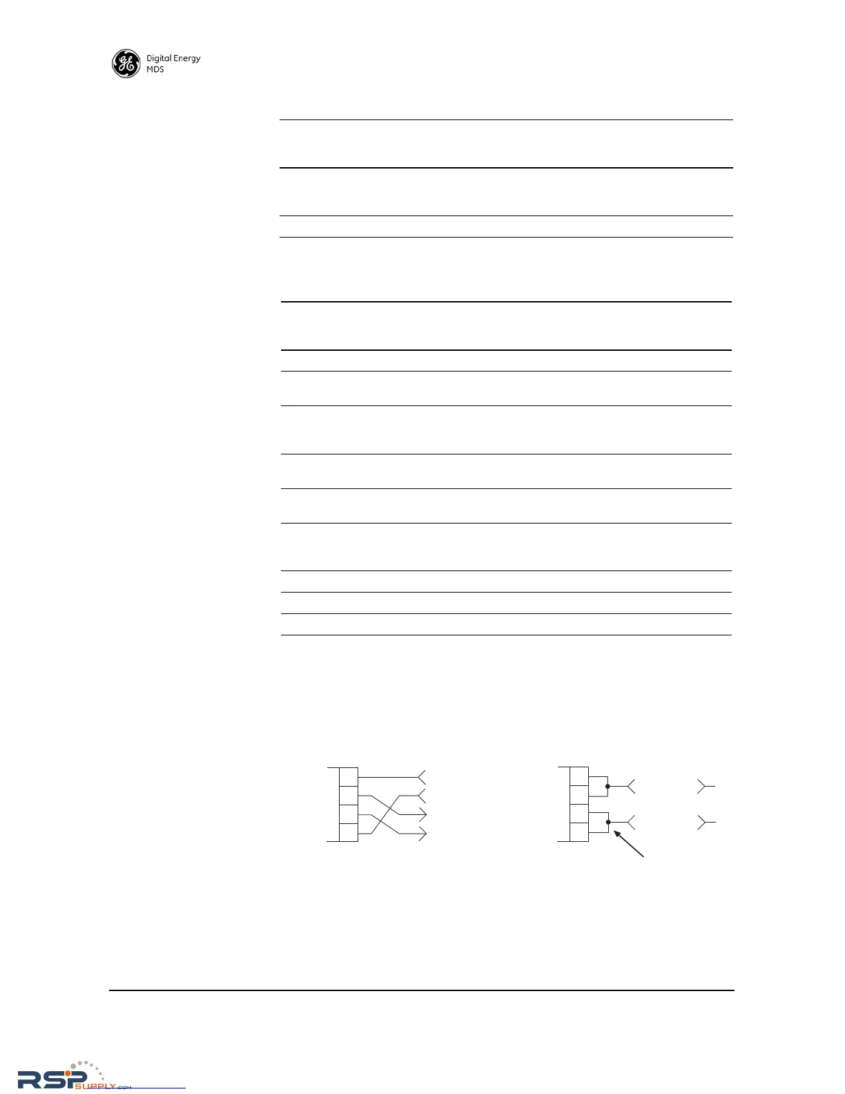
• RXD+ / RXA and RXD– / RXB are data sent into the radio to be transmitted out
• RXD+ / RXA is positive with respect to RXD– / RXB when the line input is a “0”
• TXD+ / TXA and TXD– / TXB are data received by the radio and sent out
• TXD+ / TXA is positive with respect to the TXD– / TXB when the line output is a “0”
Invisible place holder
Figure 20. RS-422/485 Wiring Arrangements
8OUTCTS (Clear-to-Send)—Goes “high” after the programmed
CTS delay time has elapsed (DCE), or keys another
connected radio when RF data arrives (CTS KEY).
9 -- Reserved—User I/O for special applications
Table 9. COM2 Pin Descriptions—Radio in RS-422/485 Mode
Pin
Number
Radio
Input/
Output
Pin Description
1OUTCarrier Detect/Link—A low indicates signal received.
2OUTTXD+/TXA (Received Data +)—Non-inverting driver output.
Supplies received payload data to the connected device.
3INRXD+/RXA (Transmitted Data +)— (Transmitted Data +).
Non-inverting receiver input. Accepts payload data from the
connected device.
4INSleep Mode Input—Grounding this pin places the radio in a
low power consumption mode.
5--Ground—Connects to ground (negative supply potential) on
the radio’s PC board.
6OUTAlarm Output—Behavior is user-configurable. Default
behavior: A high on this pin indicates an alarm condition; a low
indicates normal operation.
7INRXD-/RXB (Transmitted Data -)— Inverting receiver input
8OUTTXD-/TXB (Received Data -)—Inverting driver output.
9 -- Reserved—User I/O for special applications
Table 8. COM2 Pin Descriptions—Radio in RS-232
Pin
Number
Radio
Input/
Output
Pin Description