MDS 05-4846A01, Rev. D SD Series Technical Manual 21
means of accessing the transceiver through the built-in SD Device Man-
ager.
Telnet may also be used on this connector, and provides the same
menu-based user interface available via COM1. If you wish to use Telnet
for radio control, refer to the SD Serial/Telnet Management Supplement,
Part No. 05-6193A01.
Various options are available for passing Ethernet data on this con-
nector, allowing system administrators to optimize the configuration for
maximum narrowband efficiency, based on the operating characteristics
of their system.
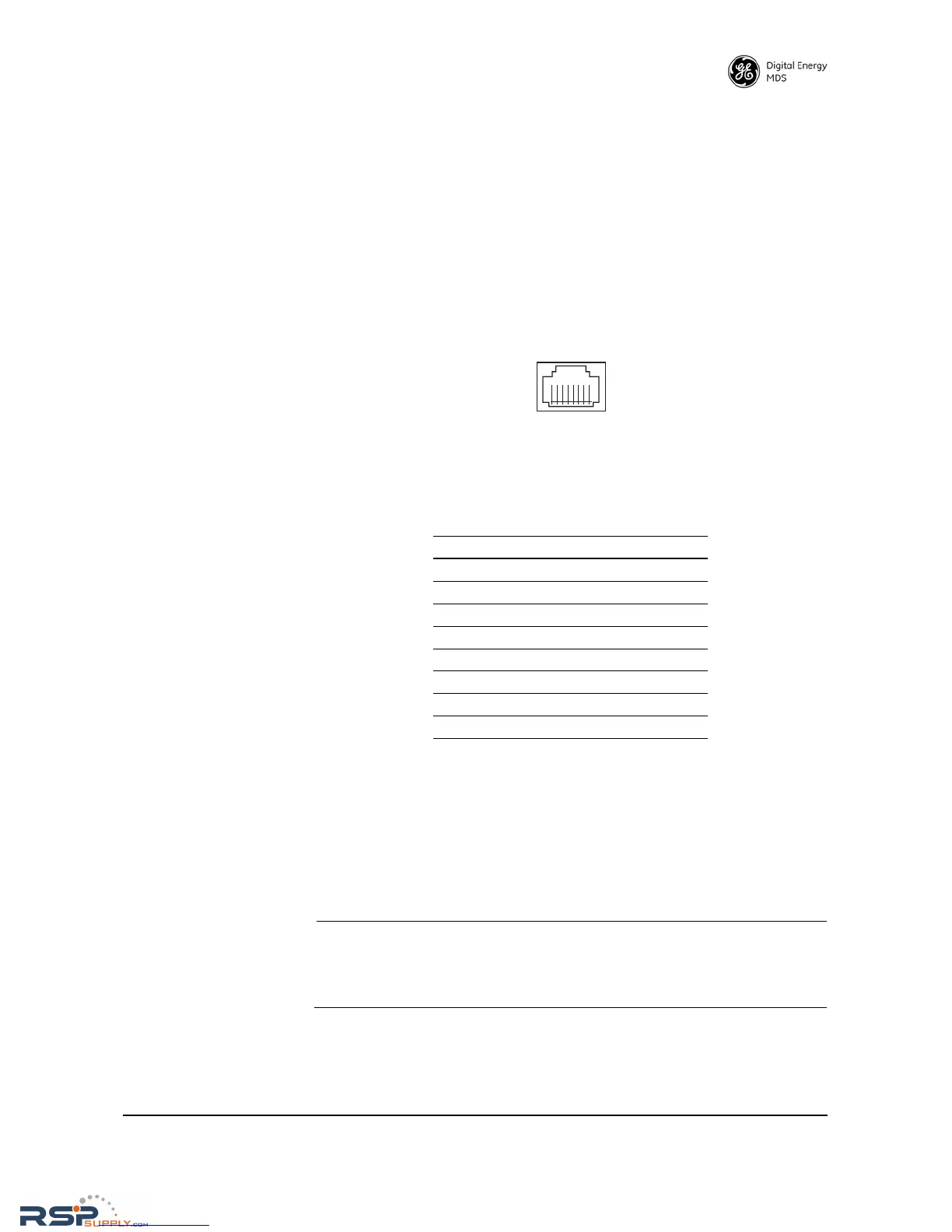
Figure 16. Ethernet Port (RJ-45) Pinout
(As viewed from the outside of the unit)
4.6 Serial Data Interfaces
COM1 and COM2 on the front panel serve as the serial interface ports for
radio management and payload data, respectively. The following sec-
tions identify the pin functions used on each interface. These ports are
user-configurable for specific applications. The procedures for changing
their default operation are provided later in this guide.
NOTE: Not all PCs have a serial port. If one is not available, a
USB-to-Serial adapter and appropriate driver software may be
used to provide serial connectivity. These adapters are avail-
able from several manufacturers, including GE MDS.
Table 6. Ethernet Port (IP/Ethernet) Pinouts
Pin Functions Ref.
1 Transmit Data (TX) High
2 Transmit Data (TX) Low
3 Receive Data (RX) High
4 Unused
5 Unused
6 Receive Data (RX) Low
7 Unused
8 Unused