8-46 Section 8-4 - System Modules- Replacement Procedures
D
IRECTION 5771498-100, REVISION 6 VENUE™ SERVICE MANUAL
PRELIMINARY
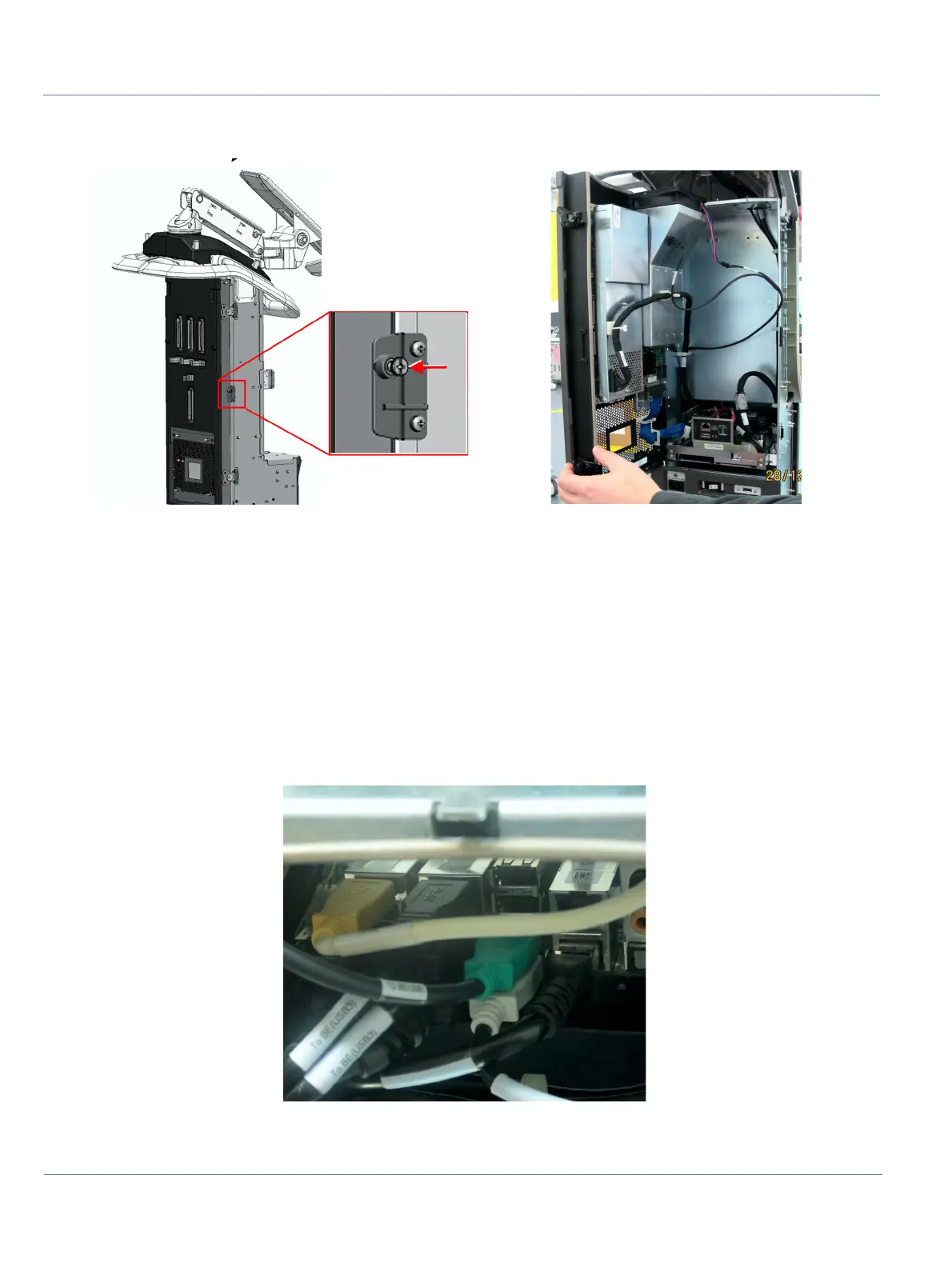
5.) Open the two fastening latches on the left side of the FE door assembly and loosen the captive
screw. Then, carefully open the door.
6) Secure the door with door support.
7.) Disconnect the following cables connected to the BE module:
• MPB to BIB
• MPB to BEP (white USB cable)
• Cockpit to BEP split cable (green and black)
• Printer cable (yellow)
• ECG USB cable.
8.) Disconnect the MPB to BE power cable.
Figure 8-31 Opening Scanner Door
Figure 8-32 Disconnecting Cables Connected to BE Module
 Loading...


