page | 15
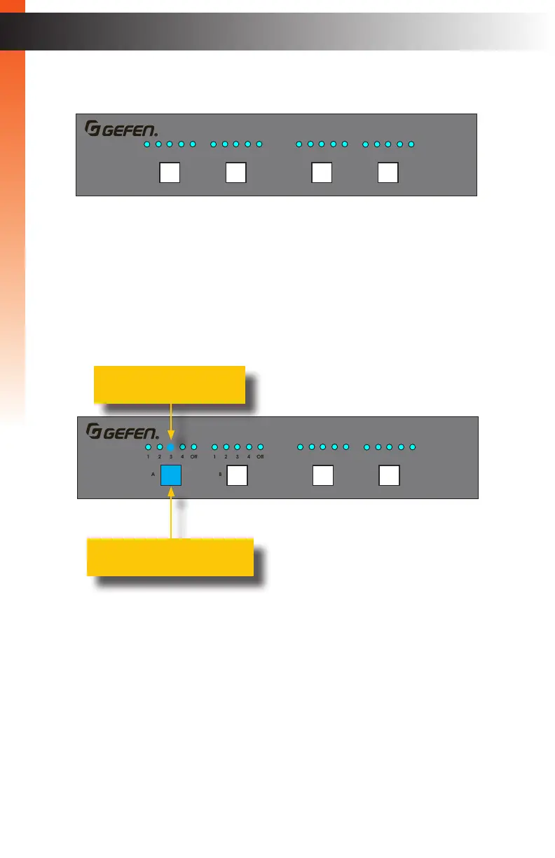
On the top-left portion of the matrix, there are four sets of ve LED indicators. Each set of
ve LED indicators resides above each of the four output buttons.
LED indicators 1 through 4 represent each input on the matrix. If one of these LED
indicators are illuminated, then that means that the input is active.
The “Off” LED indicates that the output is turned off (masked). Refer to Masking /
Unmasking Outputs (page 18) for more information on masking and unmasking outputs.
Each of the output buttons are used to route inputs to outputs. When an output button is
illuminated, it represent the currently selected output. For example, in the illustration below,
Input 1 has been routed to Output A:
In addition, in the above illustration, Input 2 is routed to Output B, Input 3 is routed to
Output C, and Input 4 is routed to Output D. If the number of the input is the same as the
number of the output, then this is called the “one-to-one” routing state. This is the factory-
default routing state of the matrix.
Basic OperationBasic Operation
Viewing the Routing Status
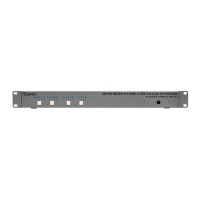
Ultra HD 600 MHz 4x4 Matrix w/HDR and Audio De-Embedder
4K 60 Hz 4:4:4, HDMI 2.0, HDCP 2.2
1 2 3 4 Off 1 2 3 4 Off 1 2 3 4 Off 1 2 3 4 Off
A B C
D
Reset Power
Out DOut COut BOut AIn 4In 3In 2In 1
LRP
Out A
Out B Out C
Out D
RS-232
IP Control
USB Power
EXT-UHD600A-44
IR In/Ext
L/R L/R L/R
L/R
24V DC
DS US DS US
USB
USB
LED indicates that Input 3
is the active input
Indicates that Output A is the
currently selected output
Ultra HD 600 MHz 4x4 Matrix w/HDR and Audio De-Embedder
4K 60 Hz 4:4:4, HDMI 2.0, HDCP 2.2
1 2 3 4 Off 1 2 3 4 Off 1 2 3 4 Off 1 2 3 4 Off
A B C
D
Reset Power
Out DOut COut BOut AIn 4In 3In 2In 1
LRP
Out A
Out B Out C
Out D
RS-232
IP Control
USB Power
EXT-UHD600A-44
IR In/Ext
L/R L/R L/R
L/R
24V DC
DS US DS US
USB
USB
 Loading...