86
all 8 analog inputs, you have to use a splitting plug (optional) or connect the sensors directly to
the Channel Inputs as described above.
If you use the sensor type SM, you may connect a second SM sensor to the input of the first
SM. You can not connect more than 2 SM sensors in line.
For connecting an alarm contact to the SM sensor, you may use the first or the second SM
contact input/output, but not both. Only one digital input/output is available per socket.
OTHER SENSORS: If you use other sensors than SM, EE or TM, you must use a splitting plug
in order to connect more than one sensor to a single INPUT of the SENSORMANAGER.
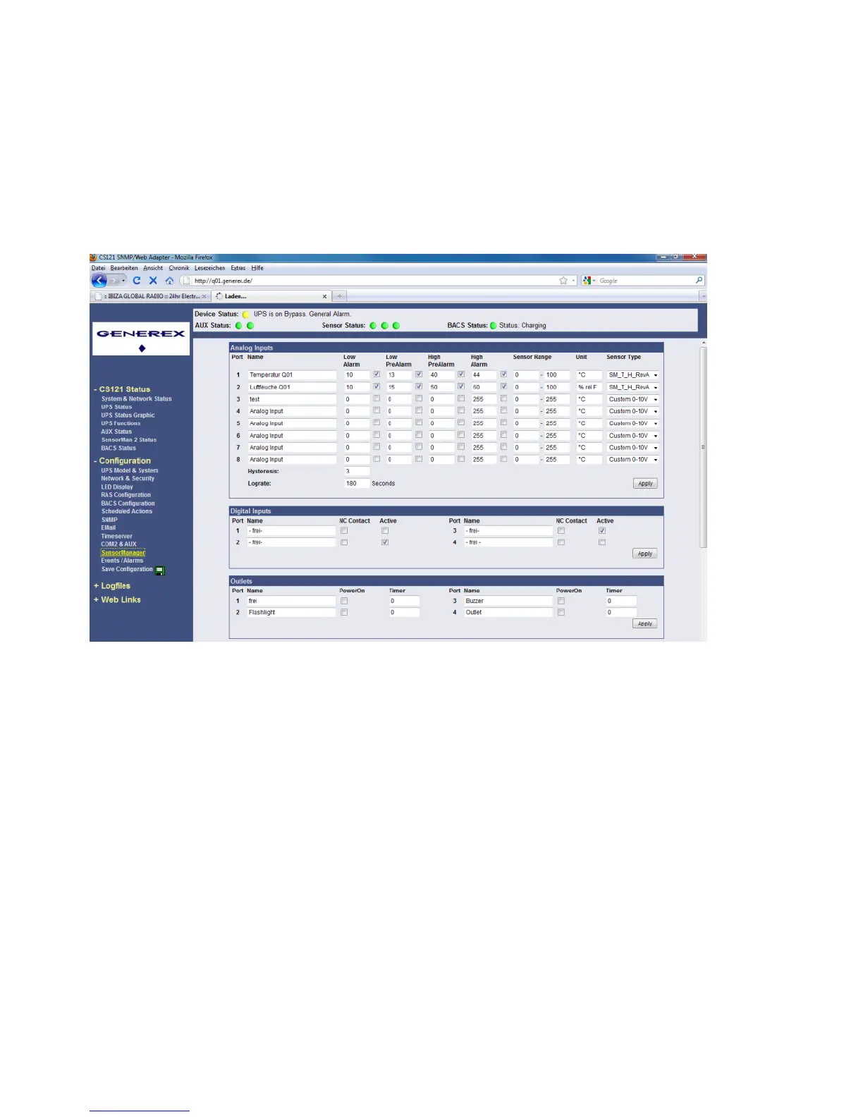
For setting up the sensors in the SENSORMANAGER make sure your configuration matches
your sensor type, e. g. see example:
Figure 104: SENSORMANAGER II Settings
Using the splitting plugs (order number SPSMRJ) it is possible to connect up to 8 sensors and
4 contacts to the SENSOR- MANAGER. A MOUNTING KIT (sold separately) is available for
affixing the SENSORMANAGER to walls and railings.
The power supply for the SENSORMANAGER may also supply an external CS121 using a
SM-CS121 type cable (sold separately) by simply connecting the POWER OUT of the
SENSORMANAGER with the POWER IN of the CS121 external.
Startup the SENSORMANAGER
Connect the sensors to the SENSORMANAGER. Connect the SENSORMANAGER using the
Mini8-DBSub9 cable to the COM 2 port of the CS121. Finally, plug the power supply into one
of the UPS power outlets. Check the LEDs on the bottom of the SENSORMANAGER; the right
one should be flashing (reading request from CS121 COM2) and the left one should be
constantly lit (power supply on). The flashing LED shows the requests from the CS121, the
other LED shows that the device has started.