87
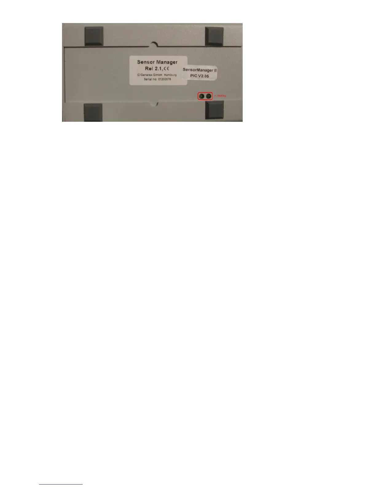
Figure 105: SENSORMANAGER II LEDs
Note: You have to configure the CS121 COM2 port to “SensorMan” (for SENSORMANAGER II
“SensorMan 2”) – otherwise the CS121 will not start making requests to the SENSOR
MANAGER.
See the CS121 user manual for instructions on how to configure the CS121 for operation with
the TEMPMAN/SENSOR MANAGER and how to manage and set the alarms.
The latest version of CS121 user manual is available for download at:
http://www.generex.de/wwwfiles/dokus/1/cs121/german/pdf/cs121.pdf
When the SENSOR MANAGER is running, you will see the values in the AUX section of the
CS121 Web browser.
Detection of the analog temperature values via variables:
#TEMP1
#TEMP2
#TEMP3
#TEMP4
#TEMP5
#TEMP6
#TEMP7
#TEMP8
Pin layout of INPUT Socket the SENSORMANAGER Box:
INPUT 1:
Pin 1 Voltage 9-24Volt +
Pin 2 Analog Channel 1 (0-10V+)
Pin 3 Analog Channel 5 (0-10V+)
Pin 4 Ground
Pin 5 OUTPUT: Open collector OUT 9-24 V, max. 30mA
Pin 6 INPUT: Digital Input 9-24V
INPUT 2:
Pin 1 Voltage 9-24Volt +
Pin 2 Analog Channel 2 (0-10V+)
Pin 3 Analog Channel 6 (0-10V+)
Pin 4 Ground
Pin 5 OUTPUT: Open collector OUT 9-24 V, max. 30mA
Pin 6 INPUT: Digital Input 9-24V