Page 4 VRC2000 Installation and Operations Manual
Technical or Setup Assistance
Telephone: 800.945.7730 (USA) or 801.975.7200 (worldwide) • Worldwide Web @ http://www.gentner.com
microwave remote supervision, machine remote control, land mobile repeater
remote control, paging transmitter remote control, low-power TV (LPTV) remote
control.
Front-Panel Controls
The VRC2000 unit was designed for ease in operation and physical hookup.
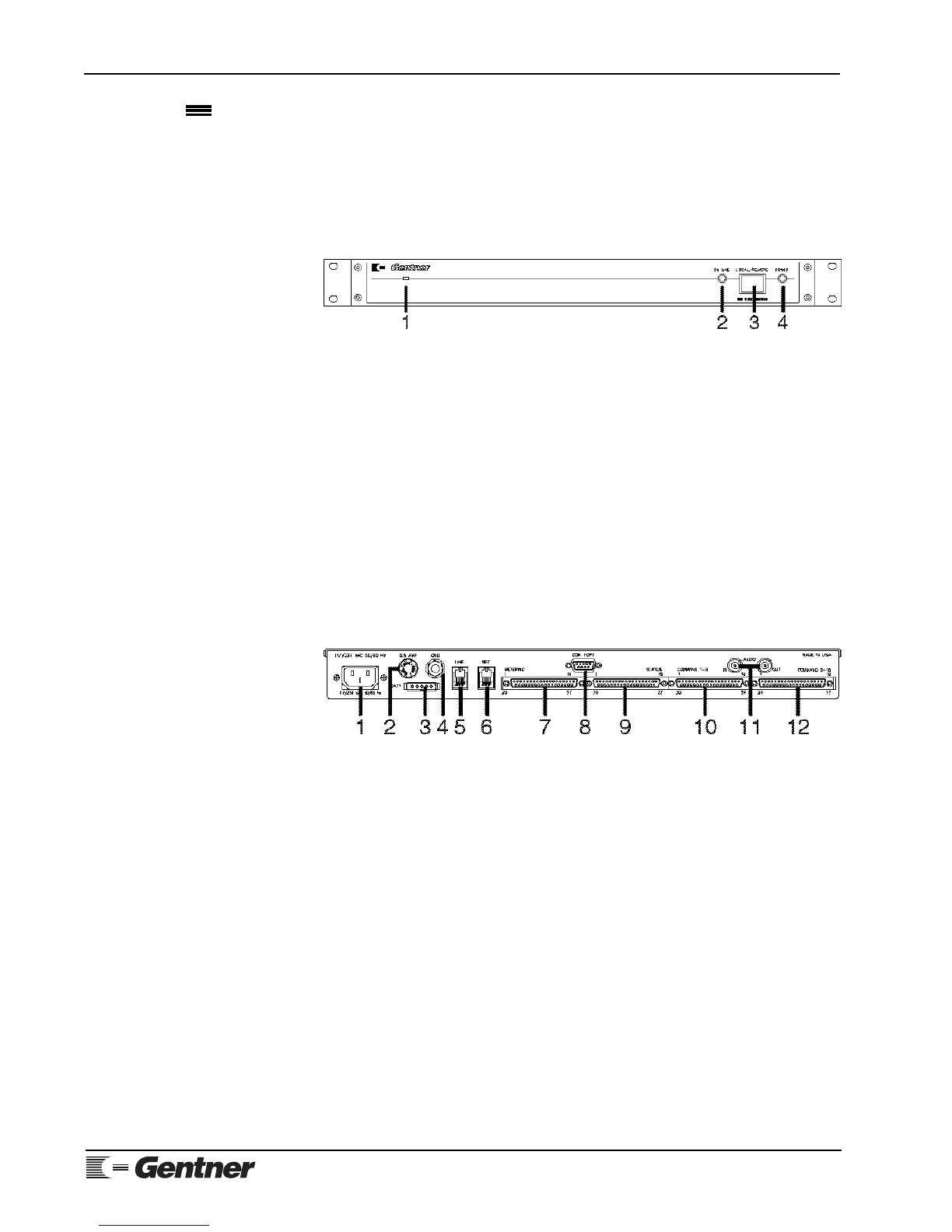
Manual operation consists of a single button and two LEDs (Figure 3,
below). The front-panel controls perform the following functions:
1. Condenser Microphone. From this opening, dial-up callers can audibly
monitor the surrounding area of the installed VRC2000 unit.
2. On Line. This LED indicates if the VRC2000 is coupled to the telephone
line in use that is plugged into the back of the unit.
3. Local/Remote. This button toggles the VRC2000 between local control
and remote operation via dial-up telephone line or using the VRC-Win
software (Windows®) or Setup VRC2000 software (DOS).
4. Power. This LED indicates if power is being supplied to the VRC2000.
Back-Panel Connectors
Following are descriptions of each of the VRC2000’s connectors (Figure 4,
below). For pinouts, see Appendix B: Connector Pinouts (Page 98).
1. Power. The VRC2000 will operate with the AC input-voltage setting of
117Vac or 234Vac.
POWER NOTE:
You must verify that your VRC2000 is set to operate from the correct AC line
voltage before plugging it in. See Initialization, Page 6.
2. 0.5 Amp. This fuse module is where the half-amp fuse is located.
3. Batt. This connector is for connection of an optional battery backup.
Gentner Communications recommends purchasing an Uninterruptible Power
Supply (UPS).
4. Gnd. This ground lug is for connection of all equipment requiring
grounding (such as the Gentner telephone surge protector).
5. Line. This RJ11C jack serves as the communication link between the
VRC2000 and a standard dial-up telephone line.
6. Set. This RJ11C jack allows a telephone set to be connected to the
VRC2000 to monitor incoming calls, place outbound calls or provide local
Product Description
Continued
Figure 3. VRC2000 front-panel
controls
Figure 4. VRC2000 back-panel
connectors