Page 68 VRC2000 Installation and Operations Manual
Technical or Setup Assistance
Telephone: 800.945.7730 (USA) or 801.975.7200 (worldwide) • Worldwide Web @ http://www.gentner.com
Before installing the VRC2000, be sure you have read and understood all sections
of VRC2000 Setup (Pages 10–67). With proper planning, all set-up parameters
can easily be configuredn in the VRC2000 prior to physical installation of the
unit with any site equipment. If the set-up process is already complete,
installation is reduced to a matter of connecting the wires.
SURGE PROTECTION NOTE:
The VRC2000 is a sensitive electronic device. In order to avoid damage to your
unit, always properly protect the VRC2000 from voltage surges over connected
telephone lines and AC power lines.
The VRC2000 is equipped with a highly reliable Telephone Surge Protector on
the telephone-line input. Gentner Communications does not guarantee that this
Telephone Surge Protector will protect the VRC2000 from damage caused by all
voltage surges; however, the Telephone Surge Protector will limit such damage.
Never disconnect or bypass the Telephone Surge Protector.
Step 1 — Determine Metering Channel Input Type
As shipped from the factory, the VRC2000’s metering-channel inputs are
ready to read voltage values with an absolute maximum range of -5–10Vdc.
However, should your application require that current values be monitored,
the metering-channel inputs can be easily switched to reading an absolute
maximum maximum range of -5–10mA.
If your application requires only voltage values to be monitored, skip to Step
2 — Metering Connections (next page). If your application requires current
values to be monitored, continue with Step 1.
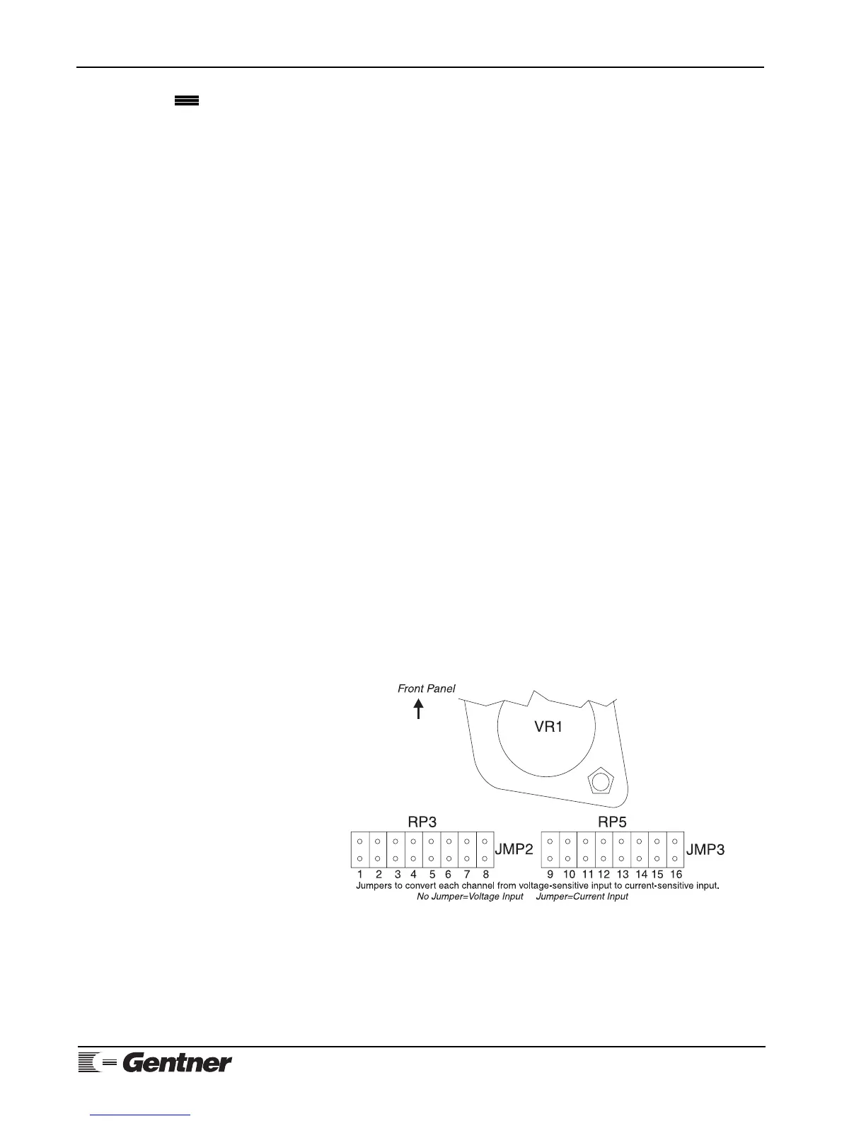
To change the metering-channel inputs to read current, place a Berg shorting
jumper (provided) across the dual row post of the desired metering channels.
Figure 13 (See below.) will in determining the proper position for the Berg
shorting jumper to change a particular metering channel from a voltage
input to a current input.
Once all metering-channel inputs requiring modification have been
jumpered, continue to Step 2.
VRC2000
Installation
Figure 13. VRC2000 metering-channel
input conversion