Page 70 VRC2000 Installation and Operations Manual
Technical or Setup Assistance
Telephone: 800.945.7730 (USA) or 801.975.7200 (worldwide) • Worldwide Web @ http://www.gentner.com
If your application does not require higher voltage capabilities, skip to Step 4
— Status Connections (below). If your applications does require higher
input values, insert the series diode as indicated in Figure 16 (previous
page).
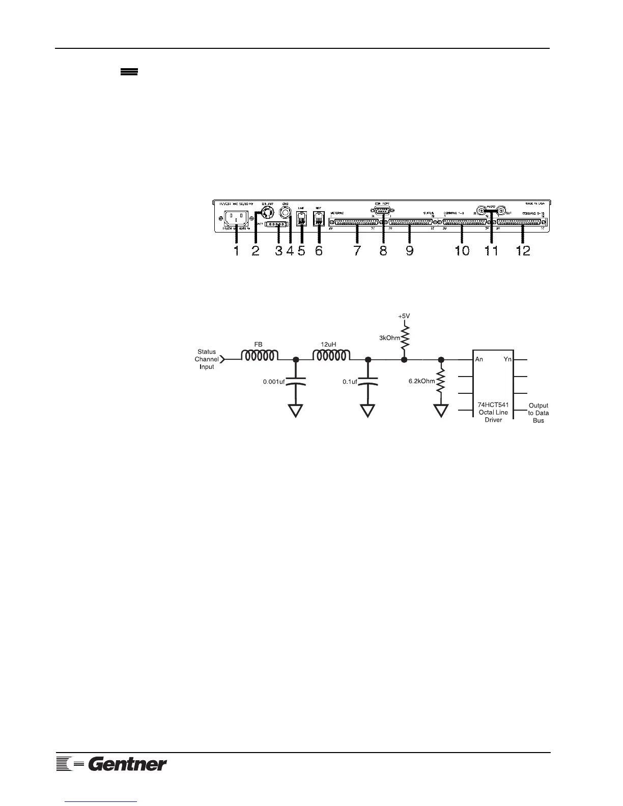
Step 4 — Status Connections
The VRC2000’s 16 status-channel inputs appear together in the DB37
connector on the rear panel labeled STATUS [9] (Figure 18, below).
For electrical specifications, see Specifications (Page 90). For Pinouts see
Appendix C: Connector Pinouts (Page 98).
The electrical diagram in Figure 19 (See below.) represents a single
VRC2000 status-channel input. Each such input is unbalanced, and is
referenced to chassis ground.
VRC2000 Installation
Continued
Figure 19. VRC2000 status-channel
input schematic
Figure 18. VRC2000 back-panel
connectors
Connect the VRC2000 STATUS connector to desired site equipment,
remembering that input levels for status channels must not exceed -.2–
5.2Vdc.
Step 5 — Command Connections
The VRC2000’s 32 command-channel outputs are broken out into two DB37
connectors [10, 12] (See Figure 18, above.) to accommodate the 16 command
channels, each with two output switches (A and B). The DB37 connectors
are labeled COMMAND 1–8 and COMMAND 9–16. For electrical
specifications, see Specifications (Page 90). For pinouts, see Appendix B:
Connector Pinouts (Page 98).
Figure 20 (next page, top) shows a single VRC2000 command-channel
output.
Connect the COMMAND 1–8 and COMMAND 9–16 connectors to desired
site equipment, remembering that command channels must not exceed
voltage of 48Vdc or sinking current of 250mA.