VRC2000 Installation and Operations Manual Page 69
Technical or Setup Assistance
Telephone: 800.945.7730 (USA) or 801.975.7200 (worldwide) • Worldwide Web @ http://www.gentner.com
Step 2 — Metering Connections
The VRC2000’s 16 metering-channel inputs are arranged together in the
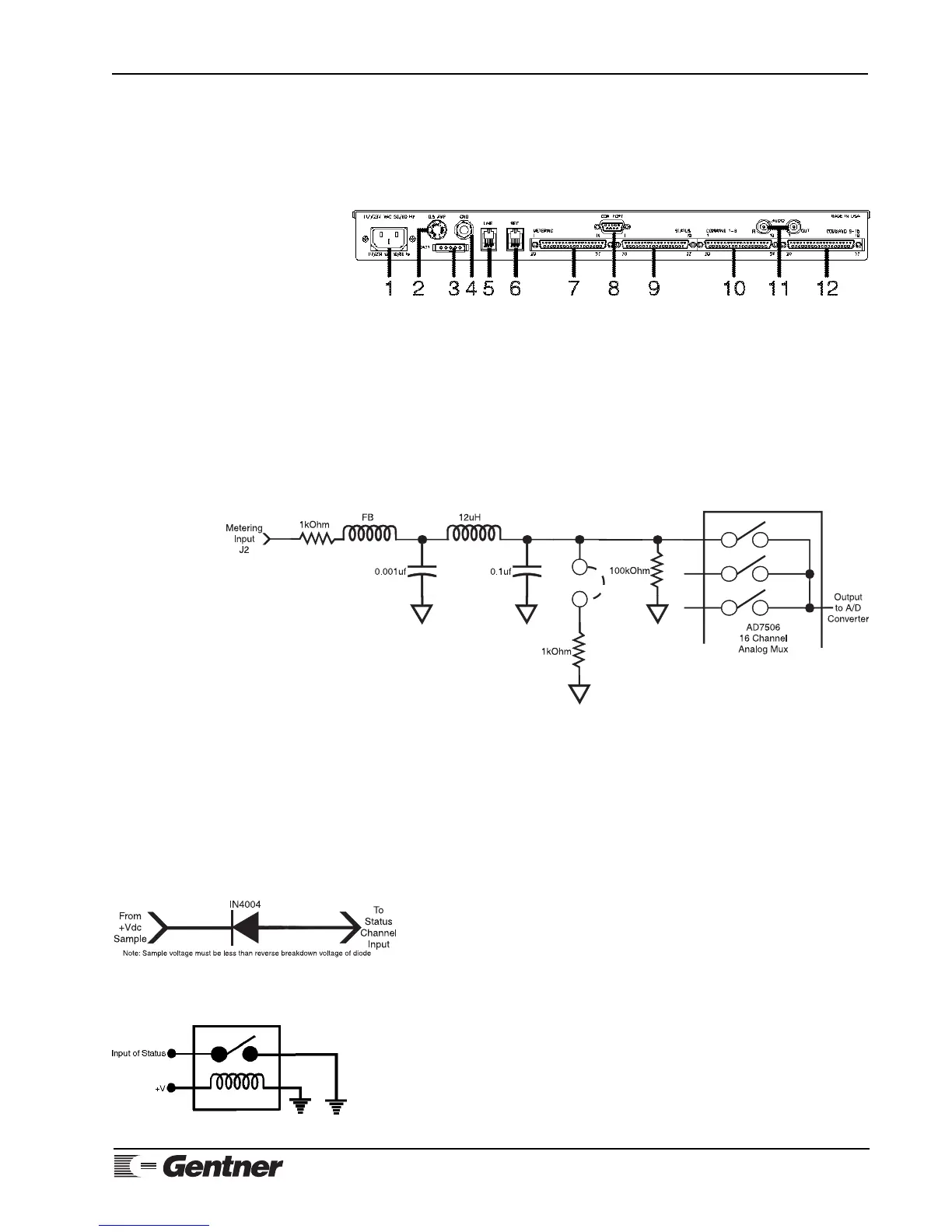
DB37 connector [7] labeled METERING on the unit’s rear panel (Figure 14,
below). For electrical specifications, see Specifications (Page 90). For
pinouts, see Appendix B: Connector Pinouts (Page 98).
Figure 14. VRC2000 back-panel
connectors
Figure 15. VRC2000 metering-channel
input schematic
Each metering channel has two programmable upper tolerance limits, and
two programmable lower tolerance limits. Each metering channel can also be
calibrated in a linear numeric value proportional to input, or a power-to-
linear input conversion. Metering channels can also be programmed to read
indirect power (the multiplication of two consecutive channels, with the
result appearing in the third channel as a new calibrated value).
Figure 15 (See below.) represents a single VRC2000 metering-channel input.
Each metering-channel input is unbalanced, and is referenced to chassis
ground.
Connect the VRC2000 METERING connector to desired site equipment,
remembering that input levels for metering channels must not exceed -5–
10Vdc (voltage reading) or -5–10mA (current reading).
Step 3 — Determine Status-Channel Input Range
When the VRC2000 takes status readings, the voltage sample is broken down
into two categories, logic 1 (open) or logic 2 (closed). How the readings is
broken down is determined by the sample itself:
0–.8Vdc = Logic 0 (closed)
2–5Vdc = Logic 1 (open)
Higher DC voltage levels can be connected to a status-channel input if a
series diode is inserted to make the open range float (Figure 16, left).
To protect the status channel from power surges, connect a relay to the input
and ground (Figure 17, left). When the relay closes, input goes low.
CLOSURE-TO-GROUND NOTE:
Without a closure to ground, each status-channel input will read open (logic 1).
Figure 17. Status-channel surge
protection
Figure 16. VRC2000 status-channel
input with series diode inserted