Page 102 VRC2000 Installation and Operations Manual
Technical or Setup Assistance
Telephone: 800.945.7730 (USA) or 801.975.7200 (worldwide) • Worldwide Web @ http://www.gentner.com
Wiring Interface
This accessory provides an alternative to standard DB37 connectors to the
VRC2000. It brings connection points to all VRC2000 status/meter/
command channels via Phioenix® connectors.
Gentner Part Number: 910-085-110
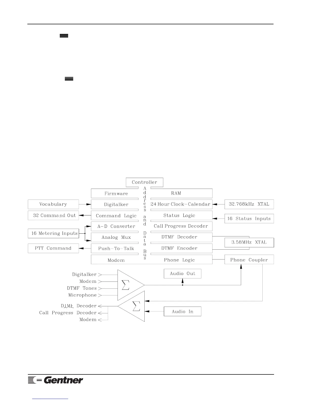
The VRC2000 is designed to provide accurate, dependable, and inexpensive
remote supervision and control of many types of equipment and facilities. The
unit uses CMOS integrated circuits to provide for low power consumption and
minimal generation of internal heat. The VRC2000 consists of the following
major building blocks:
• MC146805 Microcontroller
• Firmware (Operating System)
• Digital Voice Synthesizer
• Command Channel Outputs
• Metering Channel Inputs
• Status Channel Inputs
• Real-Time Clock
• DTMF Generator/Detector
• Telephone Interface
Figure 27 (below) is a block diagram of the VRC2000 system.
Appendix C:
Continued
Appendix D: Theory
of Operation
All circuitry is contained on a single four-layer printed circuit board (PCB).
Layers one and four (top and bottom) contain traces that convey signal-level
information. Three power-supply traces are on the third layer from the top. The
second PCB layer is exclusively the ground plane. Along with ferrite beads and
series inducters on all inputs and outputs, this design provides excellent RFI
protection.
Figure 27. VRC2000 block diagram