EasyManuals Logo

GeoVision GV-IPCamera Series User Manual

GeoVision GV-IPCamera Series
306 pages
To Next Page IconTo Next Page
To Previous Page IconTo Previous Page
Page #118 background imageLoading...
Page #118 background image
84
2. Thread an Ethernet cable (with no RJ-45 connector on one end)
from the back panel through the conduit converter (optionally
installed at step 6) and then through the cable seal.
IMPORTANT: Use the supplied ruler and leave about 10 cm of the
Ethernet cable between the connector and the cable seal.
3. Re-install the cable seal. Make sure it is installed tightly to
waterproof the camera.
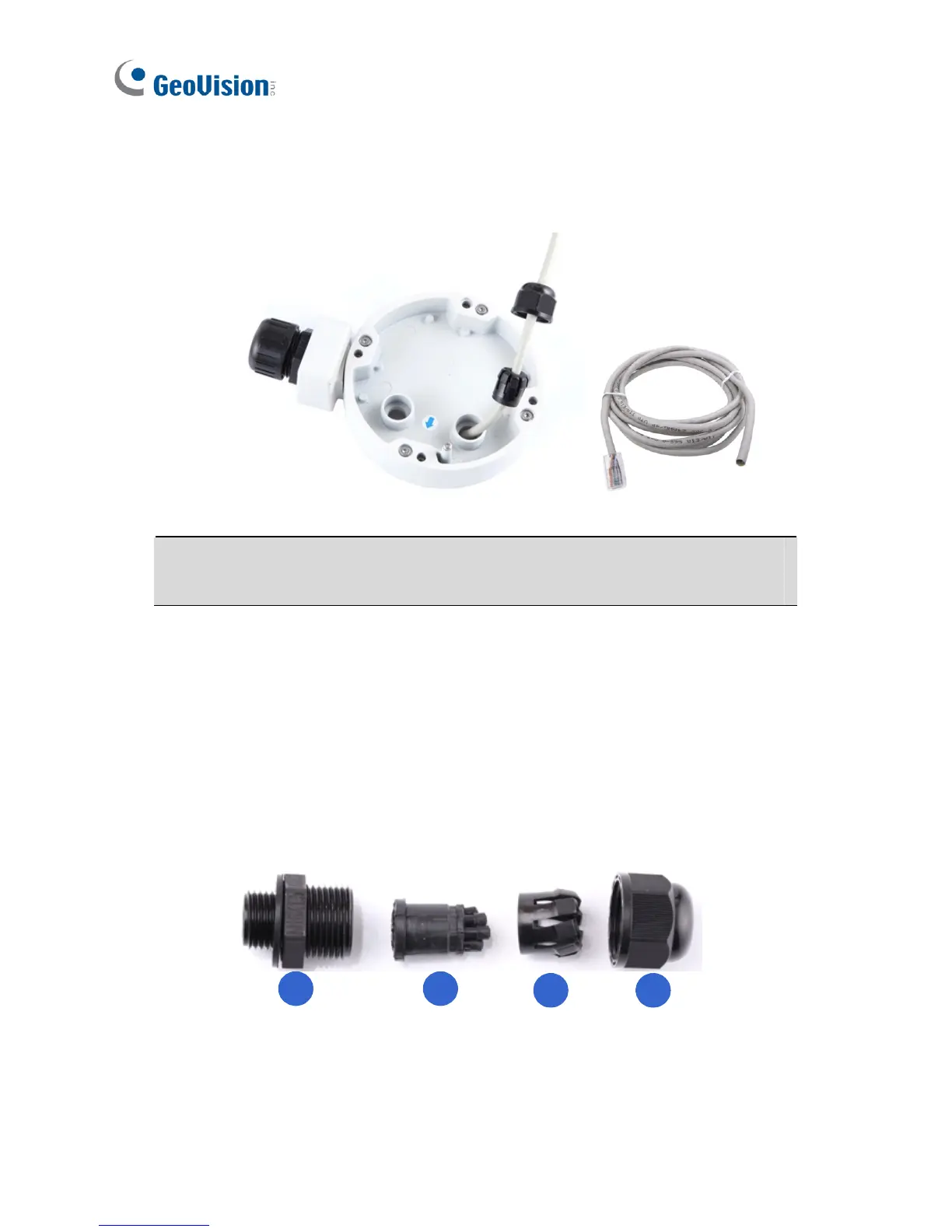
8. Thread wires into the camera.
A. Disintegrate the removed conduit connector. You should have 4
parts:
1 2
3 4
B. Remove the terminal block from the supplied power adapter.

Table of Contents

Other manuals for GeoVision GV-IPCamera Series

Questions and Answers:

Question and Answer IconNeed help?

Do you have a question about the GeoVision GV-IPCamera Series and is the answer not in the manual?

GeoVision GV-IPCamera Series Specifications

General IconGeneral
BrandGeoVision
ModelGV-IPCamera Series
CategorySecurity Camera
LanguageEnglish

Related product manuals