86
IMPORTANT:
1. Use the supplied ruler and leave about 10 cm of audio, power,
and I/O wires between their connectors and the cable seal.
2. The plugs are used to prevent water from entering the camera
housing. Keep the unused holes plugged and save the
removed plugs for future use.
3. Only thread the wires through their designated holes on the
conduit connector to make sure the wires are properly sealed.
9. Install the base to the back plate on the wall.
10. Connect the wires to the camera.
A. Install the terminal blocks to the power adapter and I/O devices.
See Power Connection and I/O Device Connections in 9.5
Connecting the Camera.
B. Install the supplied RJ-45 connector to the Ethernet cable.
C. Plug all the connectors to the camera panel.
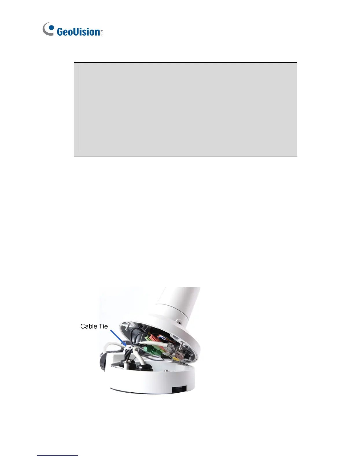
11. Tie the wires with the supplied cable tie and re-install the base to the
camera. You may need to rotate the base for the wires to fit.
 Loading...