152
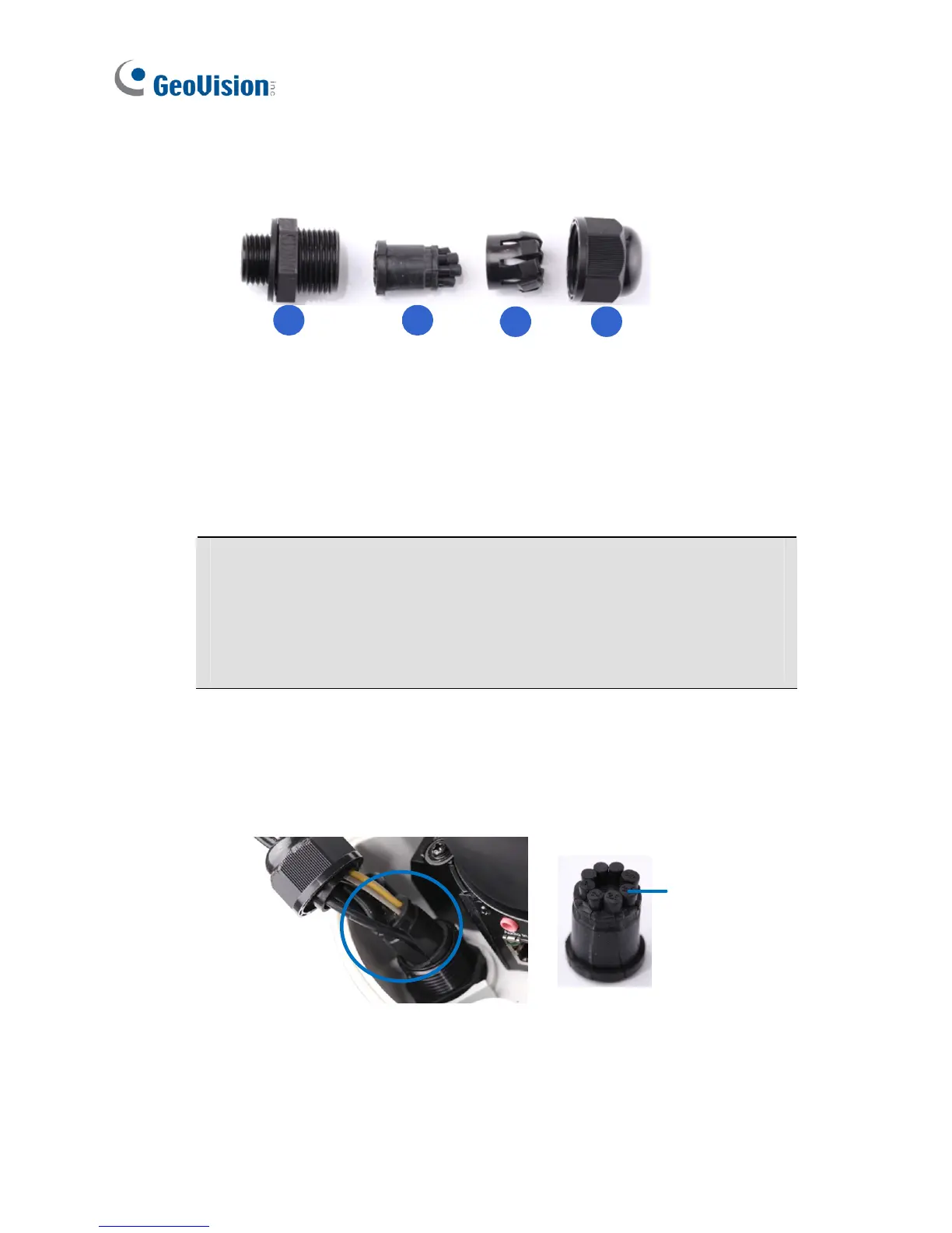
B. Unplug the conduit connector inside the housing and disintegrate
the connector. You should have 4 parts:
1 2
3 4
C. Remove the terminal block from the power adapter. (Power
adapter is not supplied for GV-VD4711 / 5711)
D. Thread the audio wires (optional), TV out wire (optional), adapter
wires and I/O wires (optional) through the conduit entry and then
through part 1, 2, 3 and 4 of the conduit connector.
Tip:
1. To make the threading easier, it is advised to thread the wires in
the order described here.
2. Use a pair of pliers to help you pull the wires through the
camera.
For part 2, there are 8 holes each labeled with its diameter.
Remove the plugs and push the wires to the corresponding hole
listed below:
Plug
 Loading...