Vandal Proof IP Dome (Part II)
153
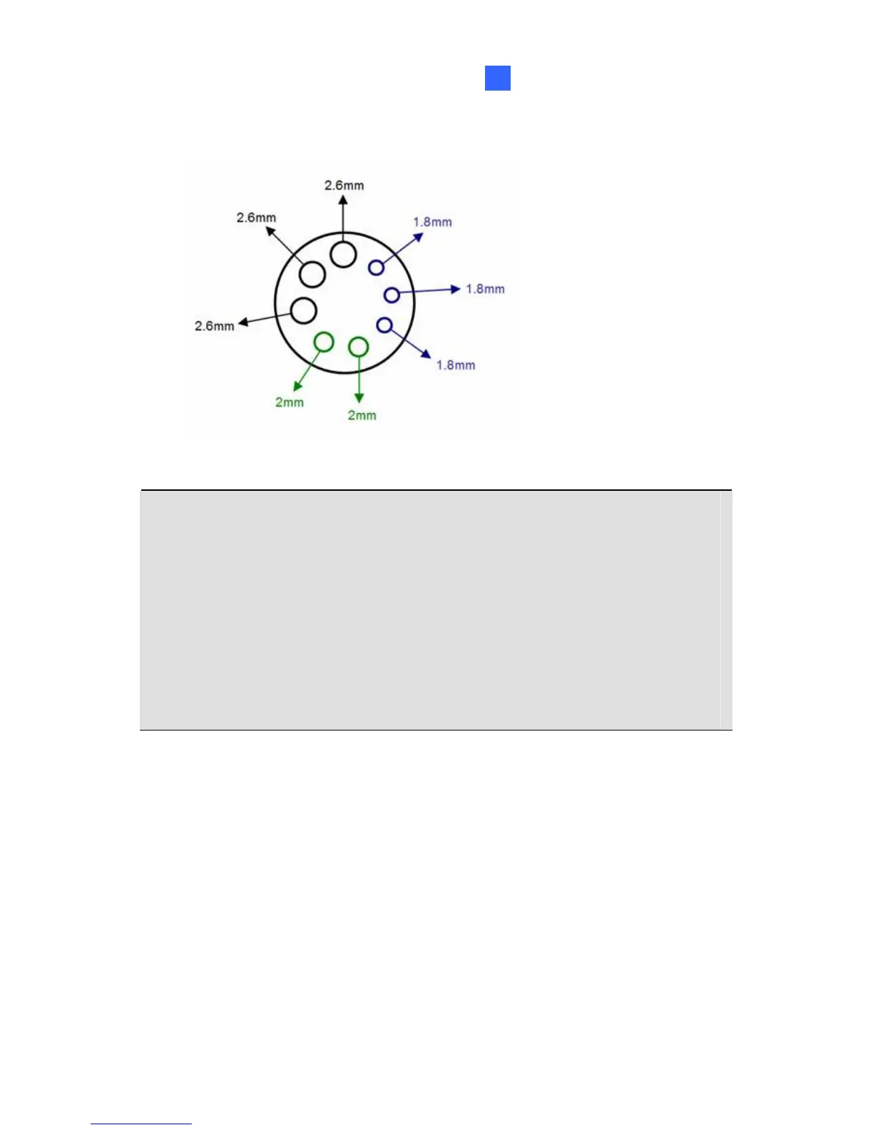
15
2.6 mm: Audio, BNC
2 mm: DC12V / AC24V
1.8 mm: DIDO
IMPORTANT:
1. Use the supplied ruler and leave about 10 cm of power and I/O wires
between their connectors and the cable gland; leave at least 11 cm
of audio/TV-out wires between their connectors and the cable gland.
2. The plugs are used to prevent water from entering the camera
housing. Keep the unused holes plugged and save the removed
plugs for future use.
3. Only thread the wires through their designated holes on the conduit
connector to make sure the wires are properly sealed.
 Loading...