EasyManuals Logo

GeoVision GV-IPCamera Series User Manual

GeoVision GV-IPCamera Series
306 pages
To Next Page IconTo Next Page
To Previous Page IconTo Previous Page
Page #189 background imageLoading...
Page #189 background image
Vandal Proof IP Dome (Part II)
155
15
4. Connect the wires to the camera.
A. Install the terminal blocks to the power adapter and I/O devices.
See 15.4 Connecting the Camera in the Quick Start Guide.
B. Install the supplied RJ-45 connector to the Ethernet cable.
C. Plug all the connectors to the camera panel.
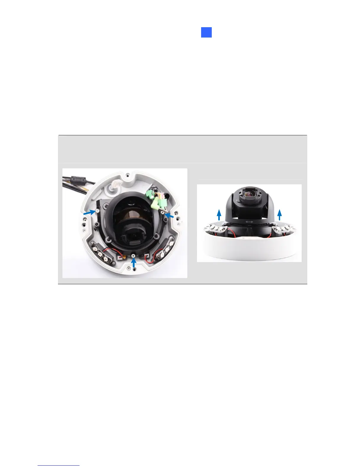
Tip: Unscrew the indicated screws and lift the camera to help you connect
the wires.
D. Arrange the wires in the conduit connector and re-install it to the
camera.

Table of Contents

Other manuals for GeoVision GV-IPCamera Series

Questions and Answers:

Question and Answer IconNeed help?

Do you have a question about the GeoVision GV-IPCamera Series and is the answer not in the manual?

GeoVision GV-IPCamera Series Specifications

General IconGeneral
BrandGeoVision
ModelGV-IPCamera Series
CategorySecurity Camera
LanguageEnglish

Related product manuals