Target Vandal Proof IP Dome
181
17
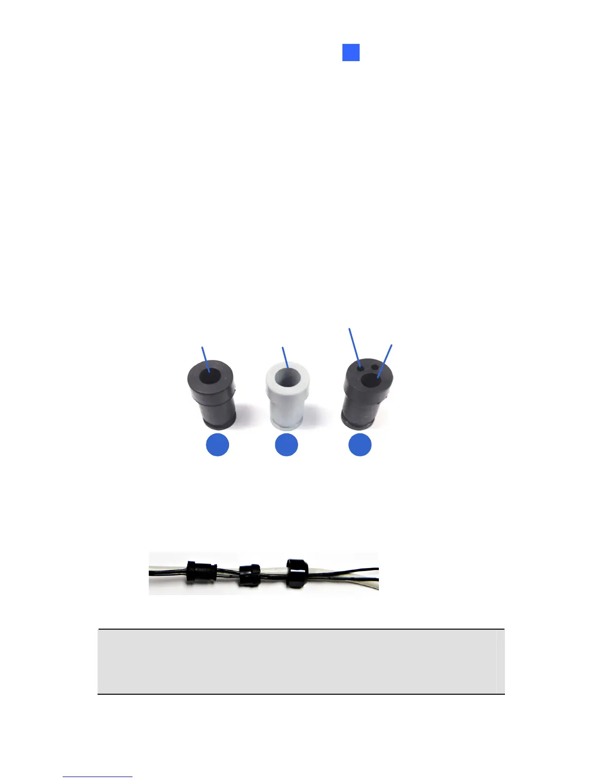
D. Thread an Ethernet cable / adapter wire through part 1 of the
connector. According to the below situation, replace the
connector if necessary.
For users of PoE with a Cat.5 Ethernet cable, stay with 1a
connector on the camera body.
For users of PoE with a Cat.6 Ethernet cable, change the 1a
connector to the supplied Waterproof rubber set (1b).
For users of DC 12V, change the 1a connector to the
supplied Waterproof rubber set (1c). Remove the terminal
block from the power adapter and thread the adapter wire
through the rubber.
re
For Ethernet cable
For Cat.5 Ethernet
cable (PoE)
For Cat.6 Ethernet
cable (PoE)
1a 1b 1c
E. Thread the Ethernet cable and/or the adapter wire through part 2
and 3 of the connector.
IMPORTANT: Use the supplied ruler and leave about 14 cm of the
Ethernet cable and 10 cm of the adapter wire between the connector
and the cable gland.
 Loading...