Target Vandal Proof IP Dome
183
17
D. Re-install the cap (part 3) with the supplied small concave
hexagon wrench. Make sure the cap is installed tightly to
waterproof the camera.
Tip: Use a pair of pliers to help you pull the wires through the
camera.
IMPORTANT:
1. Use the supplied ruler and leave about 10 cm of the audio
wires between the connectors and the cable gland.
2. The plugs are used to prevent water from entering the camera
housing. Keep the unused holes plugged and save the
removed plugs for future use.
5. Connect the wires to the camera.
A. Install the terminal block to the power adapter. See 17.4
Connection the camera.
B. Install the supplied RJ-45 connector to the Ethernet cable.
C. Plug all the connectors to the camera panel.
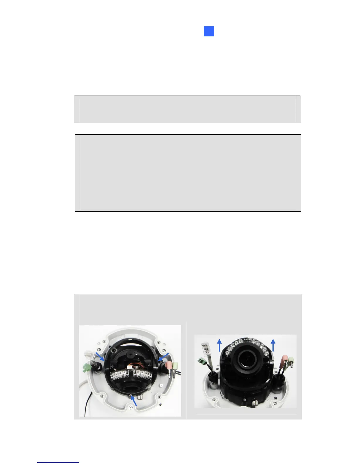
Tip: Unscrew the indicated screws and lift the camera to help you
connect the wires.
 Loading...