GM Energy V2H Bundle Installation Manual 15
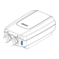
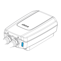
With two installers handling each, mount the Charger, the Hub, and the Inverter on their respective brackets.
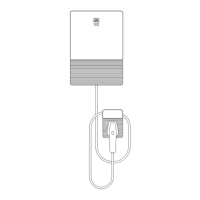
Mount the Dark Start directly to the wall surface, ensuring that the integrated cable exits from the bottom of the installed
position.
Measure for, cut, route, and attach conduit between each component (adhering to NEC requirements). Depending on
your conduit and wire routing plan, conductors and cables might enter from the back, side, or bottom of the equipment. If
rear entry raceway holes will be used on the Charger, and you are installing the Charger outdoors, first apply a rainbow-
shaped bead of sealant on the back of the Charger around the knockout.
After you have installed all appropriate fittings and raceways (conduit or tubing) route and pull all wiring into the
Inverter, the Hub, and the Charger. Communication and control wires must be minimum #18 AWG; RS485 and CAN wires
must be twisted pairs.
Note: this guide provides examples of black/white twisted pairs—other colors are acceptable if and only if they meet the
minimum specifications.
Lag screws must be minimum 1/4″ × 1 1/2″. Pilot holes shall be 60–75% of the fastener diameter (e.g. if 5/16″ lag screw
then 3/16″ pilot hole; if 1/4″ lag screw then 3/32″ pilot hole). Table 1 provides a summary of required mounting fasteners:
Sheetrock
(drywall) with
wood studs
Charger
(Holster requires 2 of same
fastener)
M8 × 60 mm (5/16″ × 2 3/8″) min. lags (qty. 2) into
framing member. Charger and holster may be center
mounted (one stud engaged) (Figure 5).
Hub and Inverter*
Blocking or plywood (minimum
5/8”) required
M6 × 76 mm (1/4″ × 3″) min. lags (Inverter min. qty. 4 at
16″ o.c.; Hub min. qty. 2 lags plus 2 anchors)
Hub may be center mounted (one stud engaged Figure
6); Inverter may NOT be center mounted.
M6 × 38 mm (1/4″ × 1 1/2″) min. lags (qty. 2) into
stud AND min. two #10 wall anchors at outer mounting
plate holes.
Charger
(Holster requires 2 of same
fastener)
M8 × 60 mm (5/16″ × 2 3/8″) min. lags (qty. 4).
Hub and Inverter*
Must have 5/8” (or thicker)
sheathing
M6 × 76 mm (1/4″ × 3″) min. lags (Inverter min. qty. 4;
Hub min. qty. 2 lags plus 2 anchors)
Sheathed
wall with
3/4″ plywood
Charger
(Holster requires 2 of same
fastener)
M8 × 60 mm (5/16″ × 2 3/8″) min. lags (qty. 4).
M6 × 76 mm (1/4″ × 3″) min. lags (Inverter min. qty. 4;
Hub min. qty. 2 lags plus 2 anchors)
Concrete,
hollow-block
CMU, or red
brick
Charger
(Holster requires 2 of same
fastener)
M8 × 60 mm (5/16″ × 2 3/8″) with anchors (qty. 4).
1/4″ × 2 3/4″ concrete screws (min. qty. 4)
3/16″ masonry
bit pilot hole
All surfaces
except concrete
1/4″ × 1 1/2″ concrete screws (qty. 2)