GM Energy V2H Bundle Installation Manual 37
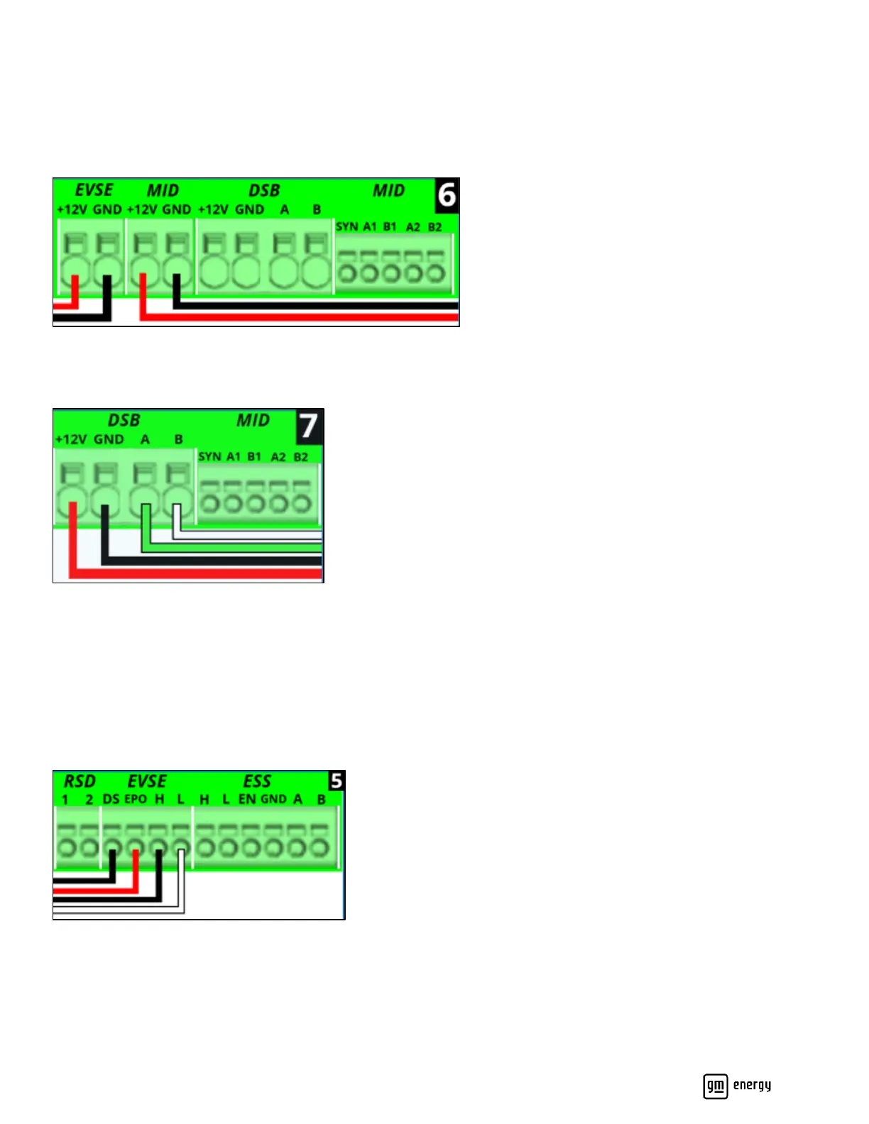
Strip the Charger conductors and the Hub conductors, add insulated ferrules (recommended), insert a flat blade
screwdriver into the lever release above the wire termination point and install the Charger conductors into the EVSE
+12V and GND terminals; and the Hub conductors into the MID +12V and GND positions (Figure 24).
Remove the screwdriver from the lever release, verify with gentle tug test, then paint mark the connection point (Figure
24, Figure 21 callout 6, and Table 5):
Figure 24: Low-voltage Charger and Hub DC connections
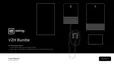
Remove the factory heat shrink on each of the four dark start conductors, then install each of those exposed conductors
into the respective DSB terminals: +12V, GND, A, and B (Figure 25, Figure 21 callout 7, and Table 5):
Figure 25: Low-voltage dark start DC connections
Wire the Comm and Control Wires
Important! Mark each twisted pair so that each is easily identifiable and distinguishable after installation.
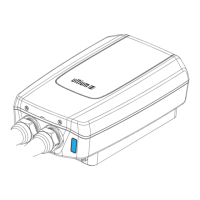
For the Charger comm and control terminations at the Inverter: strip each wire, add ferrules (recommended), and install
the following wires into the EVSE terminals: the H and L conductors routed between the Charger and the Inverter must
be a twisted pair; the DS and EPO control wires are not required to be twisted pair, but may be twisted pair (Figure 26,
Figure 21 callout 5, and Table 5):
Figure 26: Charger communication connections
For the Hub comm terminations at the Inverter: strip, add ferrules (recommended), and install the following wires into the
MID terminals: the A1/B1 wires and A2/B2 wires from the Hub must be twisted pairs. The single red SYN wire is required
for direct grid feedback from the Hub to the Inverter in the system (Figure 27, Figure 21 callout 8, and Table 5):