GM Energy V2H Bundle Installation Manual 26
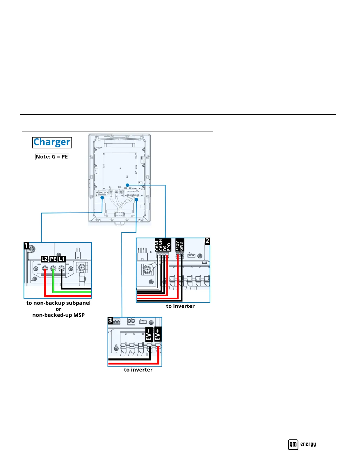
WIRE THE COMPONENTS
Referring to the diagrams and respective tables in this section, land all pulled wires and conductors; either on terminal
blocks, or by using the appropriate fasteners tightened to the correct torque value. Refer to the diagrams in this section
for termination points, and to the tables that follow each diagram for wire information. When you have completed the
wiring, reinstall the covers for the Charger, the Inverter, and the Hub.
Note: Ground (“G”) connections are sometimes labeled “PE” for protective earth. These are equivalent for purposes
of this guide.
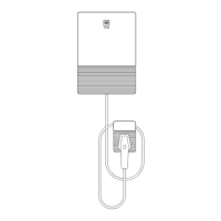
Wire the GM Energy PowerShift Charger
Figure 18: Charger wiring diagram
Charger Only
If the installation is for a standalone Charger only (no V2H Enablement Kit), route and install only the AC power circuit
conductors (Figure 18 callout 1 and Table 2).