Table 5
Important! Terminations are not in same order (R to L) in each device. And, for a given connection at the Charger, the
torque may be different than at, for example, the Inverter.
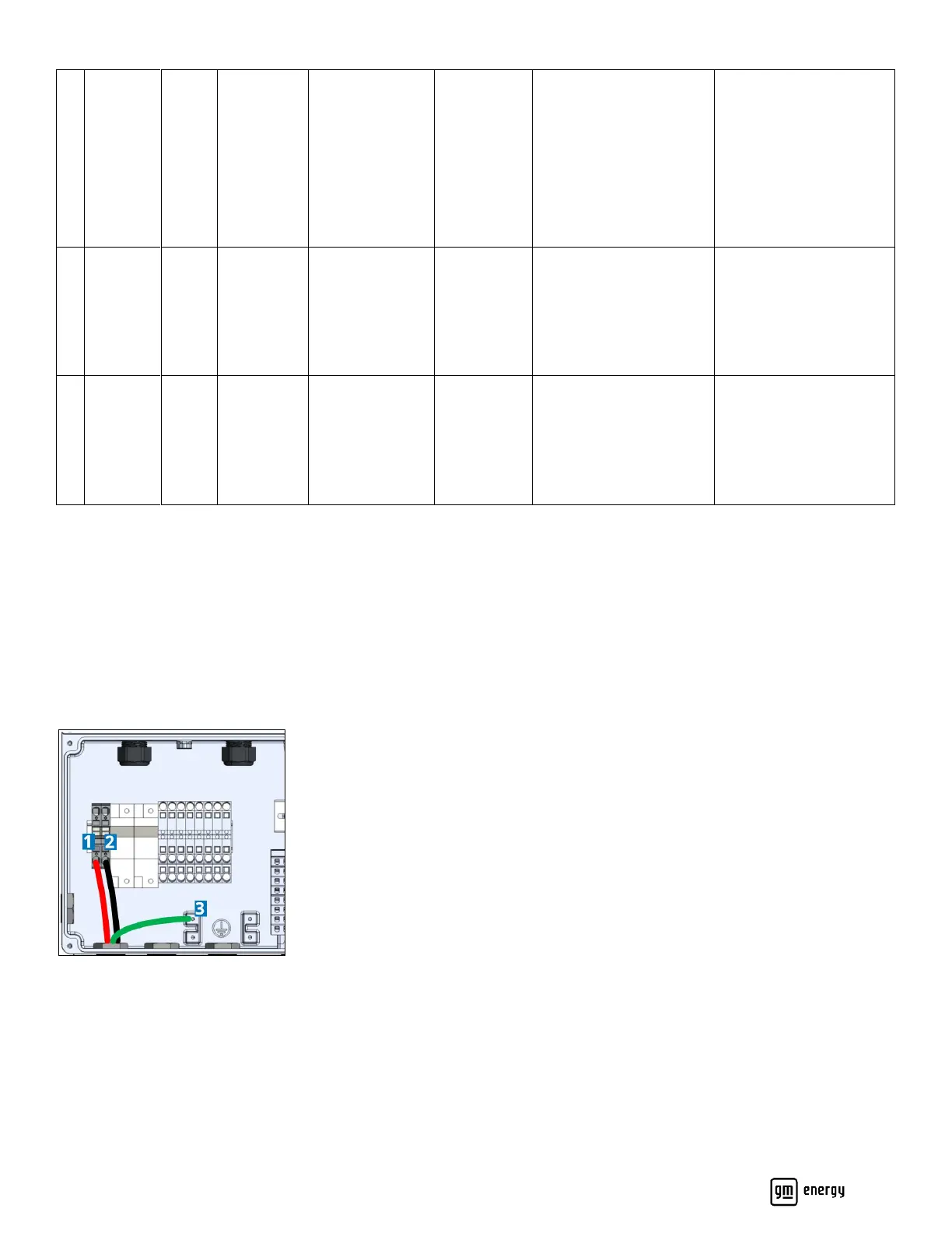
Wire the Charger Connections
Each lead must have at least 6″ inside the wiring box. Route, strip, terminate with a flat blade screwdriver at terminal
lever, perform a tug test; and then paint mark the minimum #8 AWG red and black to the terminals (Figure 21). Route,
strip, crimp on a spade terminal (recommended), terminate, torque; and then paint mark the green wire to the grounding
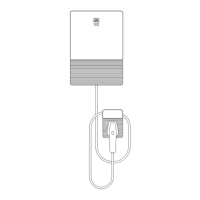
point (Figure 22 and Table 6; see also Figure 18 and Figure 21):
Figure 22: Inverter-Charger connections