GM Energy V2H Bundle Installation Manual 43
Hub–Inverter Power Wire Connection
Use only 90°C copper wire for Inverter wiring.
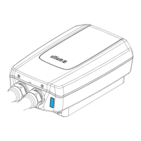
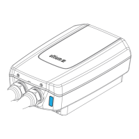
1. Install 1″ conduit into the left 1″ conduit hole on the bottom of the Hub.
2. Pull the Inverter power wires from the Inverter through this conduit into the Hub.
3. Strip and tighten the AC conductors (L1, L2, N, G) according to Figure 29 callout 2 and Table 11.
Grid Power Wire Connection
Depending on your conduit strategy, attach conduit and a watertight conduit fitting to either the 2″ Grid knockout on the
bottom right OR the 2″ Grid knockout on the side right (see Figure 8). Pull the Hub AC feeders (black L1, red L2, green
ground, and gray neutral/PE) wires through the conduit into either of the 2″ entries, and then strip 1.25” from each end.
Land the wires and tighten as per Figure 29 callout 4 and Table 5. Table 12 shows the wiring information for the
connections shown in Figure 31.