Table 6
Wire the AC Output Connections
Conduit from the AC disconnect (if present) or from the 60 A breaker in the Hub backup panel should already be
installed. If an AC disconnect is required, then mount disconnect per code requirement. The AC output (neutral) is not
bonded to ground in the Inverter.
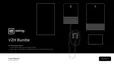
Route wiring through conduit and verify that the exposed wires are at least 6″ to provide adequate strain relief. Strip,
terminate with a flat blade screwdriver at terminal lever, perform a tug test; and then paint mark the minimum #6 AWG
red, black, and white wires into the terminals. Route, strip, crimp on a spade terminal (recommended), terminate, torque;
and then paint mark the green wire to the grounding point (Figure 23 and Table 7):
Figure 23: AC output connections
Table 7
If an AC disconnect is present, terminate the Inverter’s AC output wires appropriately inside the AC disconnect. If there is
no AC disconnect, appropriately terminate the output wires on the 60 A breaker in the Hub backup pan.
Wire the Low-Voltage DC Circuits
You should have already routed the #10 AWG red and black conductors from the Charger and the Hub, as well as the
cabled conductors from the dark start.