GM Energy V2H Bundle Installation Manual 47
TESTING AND COMMISSIONING
After all equipment is installed, it is critical that you safely verify all electrical work, energize and then verify voltage
throughout the system, commission the system, and configure the equipment.
GM Energy recommends printing the System & Voltage Checks, found in Appendix G. After all elements of the system
installation are verified, and after commissioning is complete and system operation is verified (for example, the RSD
switch operation has been verified), take a photograph of the completed sheet for job closeout records, and then fold it
up and place it inside the Hub front cover before closing and sealing the Hub door.
WARNING! This section describes verification requirements for wiring terminations and electrical
voltage checks. Prior to beginning, you must ensure that all energy sources have remained de-
energized and have had lock out tag out procedures executed.
DANGER! Circuits will be energized and tested, and will remain ON (live) during these
activities. Working with this equipment can expose individuals to severe electrical shock
hazards. Only qualified persons with appropriate PPE in accordance with NFPA 70E may perform
this work.
This section describes the following sequence of work:
1. Verifying electrical and wiring terminations.
2. Verifying low-voltage conductors and communication cables.
3. Pre-commissioning preparation.
4. Commissioning and configuration.
Verify Electrical and Wiring Terminations
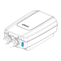
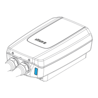
Before you begin, there must be no LED lights illuminated in the Hub, the Inverter, or the Charger. If all AC sources are
de-energized and locked out, and there is still one or more LEDs that are illuminated, open (turn OFF) the rotary PV DC
disconnect on the bottom of the Inverter. Wait 5 minutes for the Inverter to dissipate any possible stored energy.
Prior to energizing electrical equipment, review the electrical installation of raceways/conduits, conductors, and any
OCPD. Verify that raceways/conduits are adequately sealed and secured for the specific type and environment; that all
OCPDs have been installed according to design and permit; and that each is securely seated into their busbar tabs.
For the steps in this section, regarding circuit conductors, the instruction to “verify” means you must ensure ALL
of the following:
• All conductors and OCPDs are installed per requirements.
• All wires have been routed, coached, and secured so that there is no forceful pressure/bias on them or on any
respective terminal lug.
• No wiring is subject to a crush or pinch hazard—for example, the Hub hinge area and covers.
• Any spliced wires are in an appropriate enclosure, securely spliced (crimped, splice blocks torqued, or wire nuts
twisted), and fully insulated.
• Any non-metallic (NM) bundled cables are appropriately concealed.
• Any relocated multi-wire branch circuits remain paired and bundled with their neutral and ground circuit wires.
• A pull test is performed on de-energized conductors at each terminal location.