GM Energy V2H Bundle Installation Manual 38
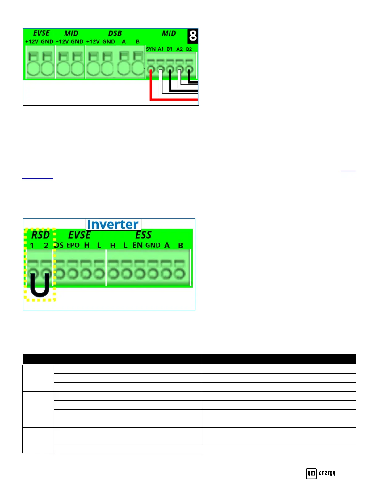
Figure 27: Hub communication connections
Wire the RSD Switch
Installation of the Rapid Shutdown Device (RSD) or Emergency Shutdown Device (ESD) is highly recommended and may
be required based on local code or ordinance. Where local code permits, it is recommended to place the RSD, clearly
labeled, near the electrical meter.
The RSD switch must be fully compliant with the Rapid Shutdown requirements of NEC 690.12. (For example, Eaton M22-
PVL-K01-R.)
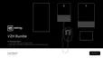
The RSD two-wire 12 VDC circuit shall be wired to a normally closed switch, so that when the switch is in the on position,
the circuit is closed. When the switch is in the OFF position, the circuit must become open. Wiring will vary based on the
switch selected by the installer. If a RSD circuit is not installed, the RSD 1 and 2 terminals must be shorted with a jumper
wire (Figure 28, and Figure 21 callout 9):
Figure 28: RSD connection
Inverter LED Behavior
The Inverter LED is located on the lower right of the front cover (Table 9).