GM Energy V2H Bundle Installation Manual 27
Route the Charger wires through the conduit, and then strip, torque, and paint mark the wires (L1, L2, PE). Verify the
connection firmly again. Note: Ensure that the Wi-Fi cable in the upper left remains secure and is not loosened when
connecting the other wires.
The Charger L1/L2 wiring must comply with the NEC Standards adopted in your region; and the wire ampacity must be
matched to the Charger DIP switch setting. Note: Some installations may not be designed for the maximum rating of
the Charger and thus may be designed with smaller gauge conductors which requires setting the DIP switches
accordingly! Always verify whether there are additional local wiring requirements such as AC disconnects and specific
labeling!
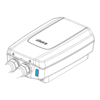
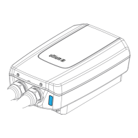
The Charger has a dark-start button on its right side. For installations that include only the Charger, the button can stop
AC charging, but it does not have dark-start capability.
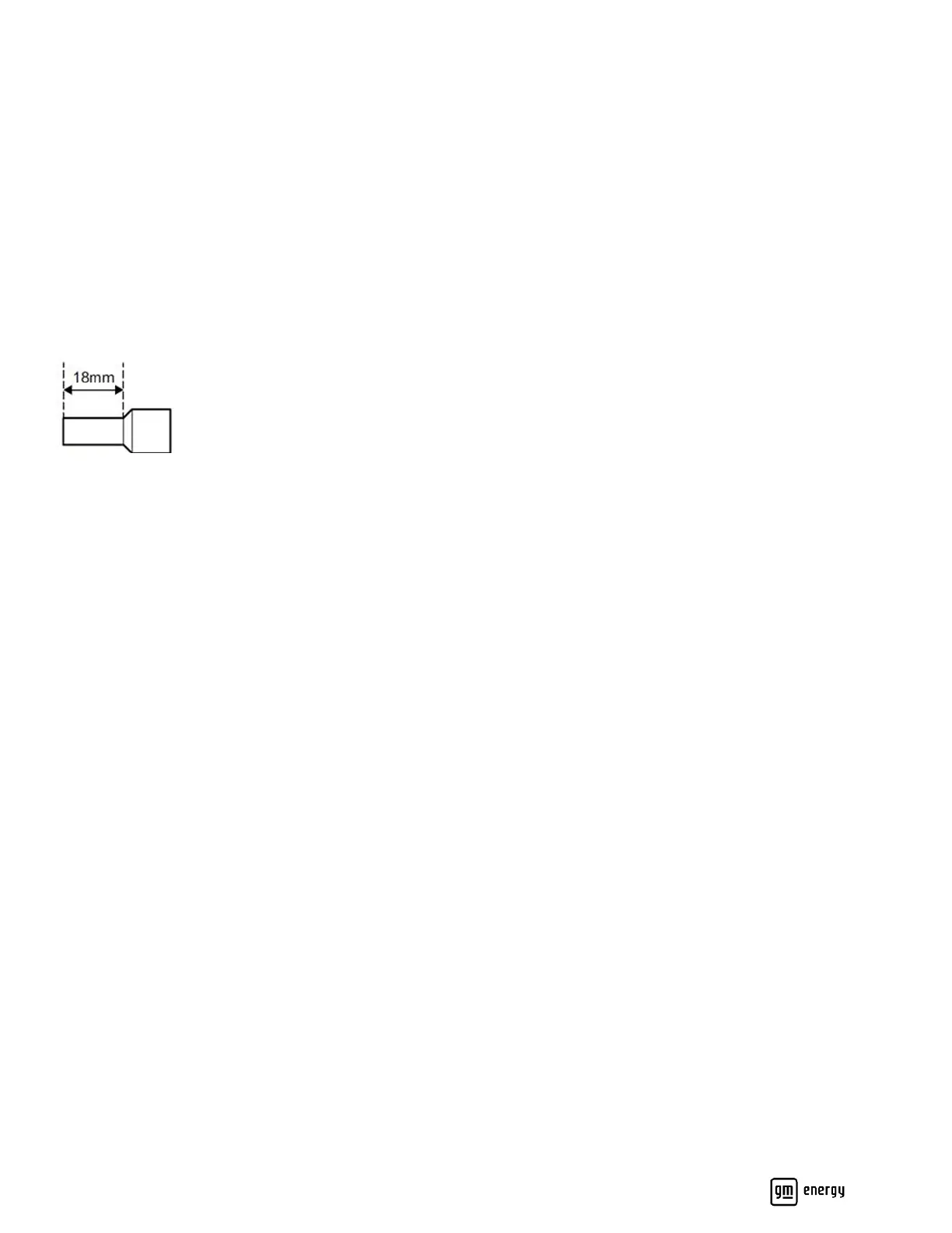
It is recommended to crimp insulated ferrules on L1, L2, PE, EV–, and EV+ terminal end. Ferrules should be sized per
conductor gauge. If ferrules are applied, strip the wires 0.71” (18mm) (Figure 19).
Figure 19: Wire strip length for ferrule crimping
Charger to Home Hub (non-backup panel)
When Charger is installed with V2H Enablement kit, the AC circuit can be routed into the non-backup panel in the Home
Hub or a non-backup subpanel. See section titled Optional Non-Backup Panel above for details.
Charger to Inverter
From the Inverter, route the comm, control, and low-voltage wires into the Charger. Strip, terminate, torque, and paint
mark the connections (Figure 18 callout 2 and Table 2):
• Min. #18 AWG twisted pair for CANL and CANH.
• Min. #18 AWG for DS and EPO.
• Min. #10 AWG for +12V and GND.
From the Inverter, route minimum #8 AWG red and black conductors to the Charger. Strip, terminate, and paint mark the
conductors into the EV− and EV+ terminals (Figure 18 callout 3 and Table 2).