GM Energy V2H Bundle Installation Manual 24
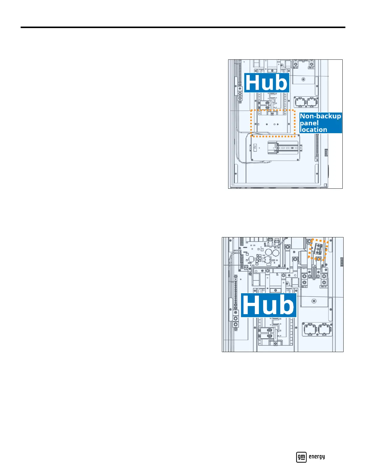
Optional Non-Backup Panel
Hub-Integrated Charger Non-Backup Panel
If a Hub-integrated Charger non-backup pan is desired, then you must
install a non-backup panel (load center) in the Hub in order to enable the
integration of the Charger. Use only an Eaton 24INT125B-1 or equivalent.
See Figure 16 and Figure 29 as well.
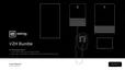
1. Position the housing block (the smaller black piece) into the hole at the
left side of the space below the central breaker area (Figure 16).
2. Fit the bussing block over the housing block.
3. Using a 5/16 nut driver, secure the two 10/32″ screws into the Hub
backplate.
4. Torque each screw to 25 in-lb and mark the connection with a paint
pen.
5. Size the wires according to the amps value you will set the Charger to
(see Section 4.2), and coach them to fit neatly along the inside of the
Hub between the main Hub PCB connector and the busing lugs on the
new non-backup load center.
6. Fabricate and install a 20″ copper L1 (black) and a 20″ copper L2
(red) power conductor to route inside the Hub, from the main Hub PCB
connector to the new non-backup panel (Figure 17):
a. At the main Hub PCB connector side:
i. Strip 1/2″ of insulation from each conductor.
ii. Install the L1 (black) conductor into the EVL1 terminal.
iii. Install the L2 (red) conductor in the EVL2 terminal.
iv. Torque each conductor in place to 35 in-lb and paint mark
each.
b. At the non-backup panel side:
i. Strip 3/4″ of insulation from each conductor.
ii. Install the L1 (black) conductor into the upper lug.
iii. Install the L2 (red) conductor into the lower lug.
iv. Torque each conductor to 45 in-lb and paint mark each.
7. Install an appropriately rated breaker. Recommended type is Eaton
BR2XXX. Refer to Appendix C for availability.
Exterior Non-Backup Subpanel from Hub
If the design includes an exterior non-backup subpanel which originates from the Hub:
1. Install the external subpanel and route raceway from it to the Hub.
2. Route the subpanel feeder conductors through the raceway into the Hub:
a. Size the conductors per rating.
b. An exterior non-backup subpanel will require installation of the Hub-integrated Charger non-backup panel.
Install branch breaker in Hub non-backup panel then route L1 black and L2 red conductors to non-backup
breaker. Terminate, torque, and paint mark terminations.
Note: Do not feed an exterior subpanel directly from the main PCB connector (EVL1 & EVL2)