GM Energy V2H Bundle Installation Manual 14
INSTALL COMPONENTS AND CONDUIT
Important! Before you begin, read the instructions in the subsequent Details sections for each component as well!
Install all components on load-bearing walls with framing members only. Do not violate environmental, clearance, or
maximum distance requirements. If you are only installing the Charger, the instructions for the other components do not
apply!
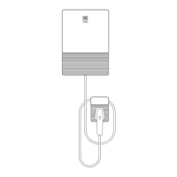
1. Carefully open each component’s box. For the Charger, Home Hub, and Inverter, remove the mounting bracket.
2. Verify that the mounting location for each piece of equipment is made of a non-flammable material, provides enough
clearance and spacing (*Dimension is recommendation
3. Figure 3 and Figure 4 and Section 1.5), and is adequate for the mounting fasteners.
4. For the Charger and Hub, use the mounting bracket as a template to mark the holes (the center holes when mounting
to a single stud), then level and mount each bracket to the wall in the designated location using the hardware
described in Table 1. All fasteners must be stainless steel, and must land in the center of the stud. For the Hub, if
mounting to drywall with studs, in addition to the two lags you install in the center of the bracket, install one drywall
anchor in one of the holes left of center and one right of center.
5. For the Inverter, use the mounting bracket as a template to mark four holes between two studs (typically the four
which are at 16″ o.c.), and then level and mount the bracket to the wall in the designated location using the hardware
described in Table 1. All fasteners must be stainless steel, and must land in the center of the stud.
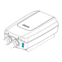
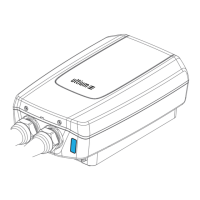
6. Remove covers to the equipment wiring chambers (you may choose to do this after you mount the equipment):
• Charger: using a T20 tool, remove the front cover by removing the two screws holding the bottom and then
carefully prying the cover off; then remove the fourteen screws and carefully remove the inner cover. DO NOT
LOSE ANY SCREWS!
• Hub: using a precision screwdriver (or 1/8 Allen wrench), gently pry open the cosmetic covers over the latches on
the right side of the Hub, and then open the latches. With a T20 tool, loosen the three dead front screws on the
left side, and then remove the three screws on the right side. Carefully pull the right side of the dead front toward
you, then slide it to the right and remove it.
• Inverter: using a T20 tool, loosen the five lower wiring chamber cover retention screws and then remove the
cover.
Note: Latch covers are optional.
Verify equipment mounting location feasibility, and remove plugs and/or prepare knockouts and fittings (as required by
conductor specifications) before mounting the equipment. Use only the factory entry locations and do not enlarge any.
To remove a conduit plug, use a flat blade screwdriver to turn the plug while at the same time holding the nut on the
inside of the wiring box.
For install locations exposed to water, use the appropriate water-tight fitting to match NEMA rating of unit. For install
locations not exposed to water any NEC compliant fitting is allowed. Each wiring entry must allow for a 6″ wire loop inside
the wiring chamber.
Raceways are required for the conductors, control cables, and communication cables that route between each piece of
equipment. For example, the Rapid Shutdown Device (RSD) control cable from the Inverter must route in an appropriate
raceway. If you are only installing the Charger, only the 120/240 V circuit (with grounding conductor) is required.