GM Energy V2H Bundle Installation Manual 25
c. Route, strip, terminate, torque, and paint mark the neutral (white) conductor into the neutral (N) bar.
d. Route, strip, terminate, torque, and paint mark the grounding (green) conductor into the positive earth (PE)
grounding bar.
3. In the exterior subpanel, power conductors must be wired into overcurrent protection device (OCPD):
a. Route L1 black and L2 red conductors into subpanel main breaker. Terminate, torque, and paint mark
terminations.
b. Route, strip, terminate, torque, and paint mark neutral (white) conductor into the neutral (N) bar.
c. Route, strip, terminate, torque, and paint mark the grounding (green) conductor into the grounding bar. the
positive earth (PE) grounding bar.
Optional Second Energy Meter (for AC Solar Integration)
Important! The GM Energy Home system is compatible with external AC solar but does not control the AC solar.
Compliance for utility interconnection must be facilitated through the installer of the external AC solar system.
The AC solar system must be connected to the non-backup panel such that solar production does not occur during a
power outage. Integration of AC solar on backup panels may be possible in the future. Please refer to most recent update
of this document found at https://gmenergy.gm.com/for-home/installation-support for further information on AC solar
integration into the backup panel. Do not rework existing solar system without proper communication with customer
and/or the previous solar system installer as existing warranty may be affected.
To support new or existing AC solar, a second energy meter must be sourced and installed into the Hub.
1. GM Energy Preferred Installers will be able to indicate need for an Acrel meter directly to GM Energy. When they do
so, it will be packaged with the rest of the Enablement Kit.
2. If you are not a Preferred Installer – or are one and did not indicate need at the outset – you may contact GM Energy
Support Center at 1-833-64POWER to obtain one.
a. If possible, this will be included with the shipment of the Enablement Kit; if the Enablement Kit has already
shipped, the Acrel meter will be sent as a separate shipment.
3. Using a #2 Phillips screwdriver, remove the four screws and remove the metal meter cover from the lower section of
the Hub.
4. Using a precision flat blade screwdriver, loosen the DIN rail retainer on the right side of the existing Acrel meter, and
slide the retainer to the right of the DIN rail.
5. Install the second Acrel meter onto the DIN rail between the existing meter and the retainer.
6. Slide the retainer to the left to secure the second meter in position, and then tighten the retainer to the DIN rail.
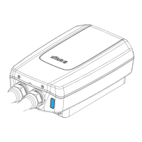
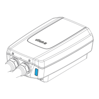
7. Secure the CTs from the second meter around the L1 and L2 solar circuit conductors
a. CTs must capture all solar generation, and are typically installed around the solar subpanel feeder circuit
conductors.
b. Orient the CTs to capture the flow of power in the correct direction (CT arrow should point away from solar
inverter)
c. Install the L1 CT around the L1 conductor, and the L2 CT around the L2 conductor.
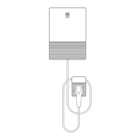
8. Wire the second meter to the Hub controller board in the upper right of the Hub.
9. Re-install the metal meter cover.