GM Energy V2H Bundle Installation Manual 32
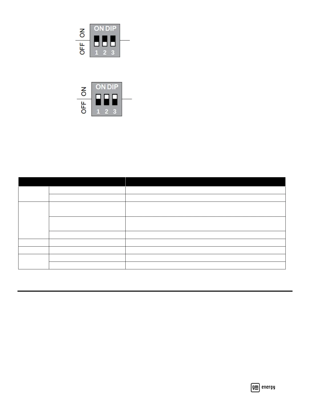
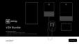
3. Deenergize the Charger again and set the DIP switch pins to the new amperage of the installation, using Table 3
as a reference. Here, the DIP switch setting is 111, corresponding to an 80A output current.
4. Turn on the breaker to power on Charger. When the LED is solid white, plug the charging gun into the EV to start
the charging.
5. The installer can use the commissioning app to confirm that the DIP switch setting has been successfully changed.
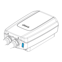
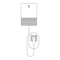
Charger LED Behavior
For system alarm codes, refer to the GM Energy V2H System Troubleshooting Guide. The Charger LED is located on
the lower right of the front cover (Table 4):
Charger is Initializing (at install or after reset)
Charger is Ready (unplugged).
BLINKING
(1 second on , 1 second off)
BLINKING
(1 second on , 4 seconds off)
Charger is Ready (plugged in, not charging)
Discharge Session Initializing
Firmware Update in Progress
Charger Error (refer to installation manual)
Installation Not Complete (DIP switch not set).
Table 4
Wire the Inverter
Before beginning to wire the Inverter, ensure that no live voltages are present on PV input and AC output circuits, and
verify that the DC disconnect on the bottom of the Inverter, the AC disconnect, and the dedicated AC branch circuit
breaker are all in the OFF (open) position! If there is no rapid shutdown (RSD) switch installed, ensure that RSD 1 and
RSD 2 are jumpered together (Figure 21, callout 5 and callout 9).