5
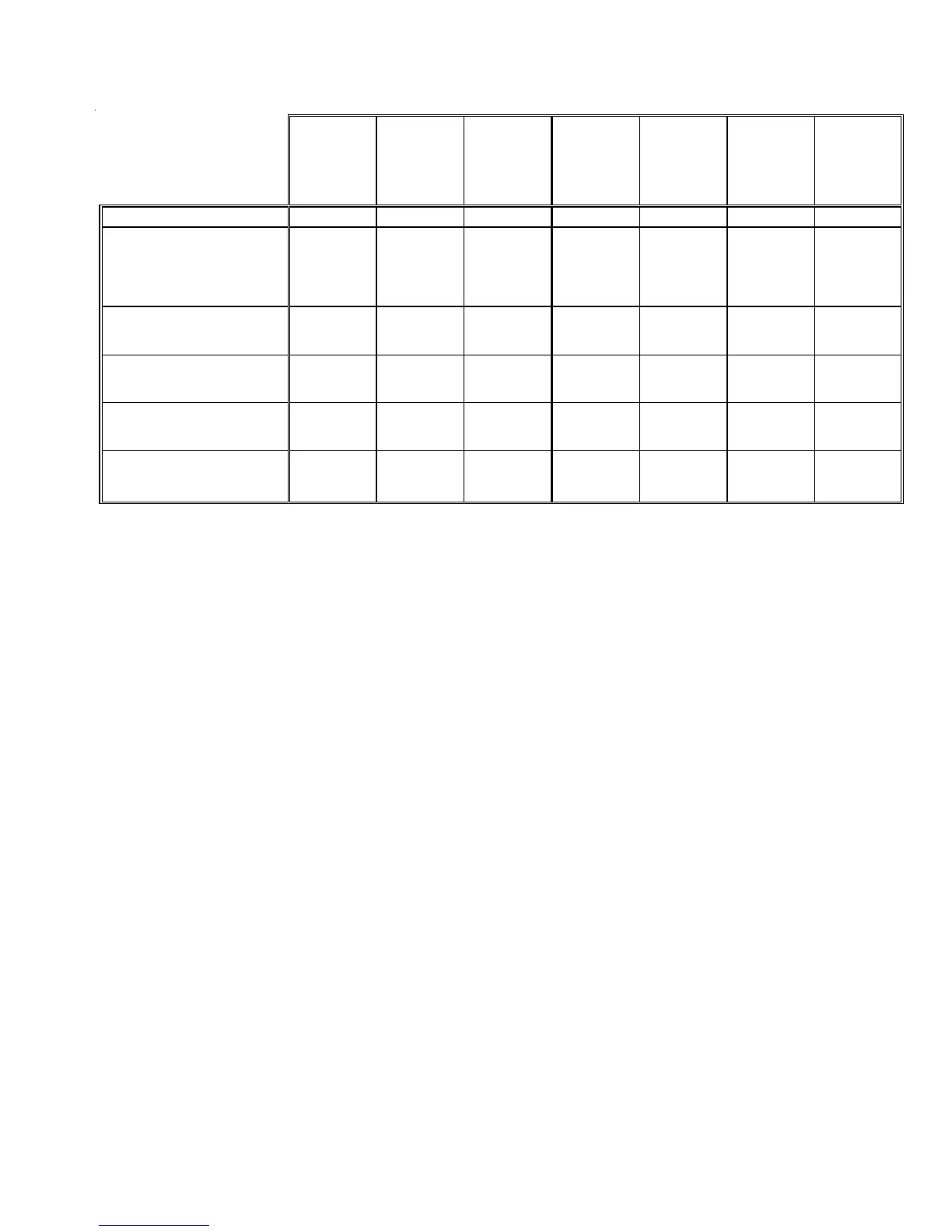
HEAT PUMP SPECIFICATIONS GSH14[018-060]1A*
(1)
Wire size should be determined in accordance with National Electrical Codes. Extensive wire runs will require larger wire sizes.
(2)
Must use fuses or HACR-type Circuit Breakers of the same size as noted.
NOTES:
* Always check the S&R plate for electrical data on the unit being installed.
* Installer will need to supply 7/8" to 1 1/8" adapters for suction line connections.
* Unit is charged with refrigerant for 15' of 3/8" liquid line. System charge must be adjusted per Installation Instructions Final Charge Procedure.
* Installation of these units that require a TXV Kit to be installed on the indoor coil:
PLEASE NOTE: THE SPECIFIED TXV IS DETERMINED BY THE OUTDOOR UNIT NOT THE INDOOR COIL
NOTE: This data is provided as a guide, it is important to electrically connect the unit and properly size fuses/
circuit breakers and wires in accordance with all national and/or local electrical codes. Use copper wire only.
GSH140181A*
GSH140241A*
GSH140301A*
GSH140361A*
GSH140421A*
GSH140481A*
GSH140601A*
Cooling Capacity, BTUH 18,000 24,000 28,000 36,000 39,500 46,000 55,000
Compressor
R.L. Amps 9 10.9 12.2 13.4 16 18.3 19.8
L.R. Amps 41.0 54.0 63.0 73.0 88.0 109.0 137.0
Loss of Charge Pressure Switch
Open / Close 7 PSIG/25 PSIG 7 PSIG/25 PSIG 7 PSIG/25 PSIG 7 PSIG/25 PSIG 7PSIG/25 PSIG 7 PSIG/25 PSIG 7PSIG/25 PSIG
Condenser Fan Motor
Horsepower 1/12 1/6 1/6 1/4 1/4 1/4 1/4
F.L. Amps 0.6 1.1 1.1 1.5 1.5 1.5 1.5
Liquid Line, Inches O.D. 3/8" 3/8" 3/8" 3/8" 3/8" 3/8" 3/8"
Suction Line, Inches O.D. 3/4" 3/4" 3/4" 7/8" 7/8" 7/8" 7/8"
Refrigerant Charge 160 160 165 220 220 280 285
Power Supply 208/230-60-1 208/230-60-1 208/230-60-1 208/230-60-1 208/230-60-1 208/230-60-1 208/230-60-1
Minimum Circuit Am
acit
(1 )
11.8 14.7 16.3 18.3 21.5 27.8 27.3
Maximum Overcurrent Device
(2)
20 20 20 30 30 40 40
Electrical Conduit Size
Power Supply (Inches) 1/2 or 3/4 1/2 or 3/4 1/2 or 3/4 1/2 or 3/4 1/2 or 3/4 1/2 or 3/4 1/2 or 3/4
Approximate Shipping Weight 199 207 207 242 242 266 280
 Loading...