62
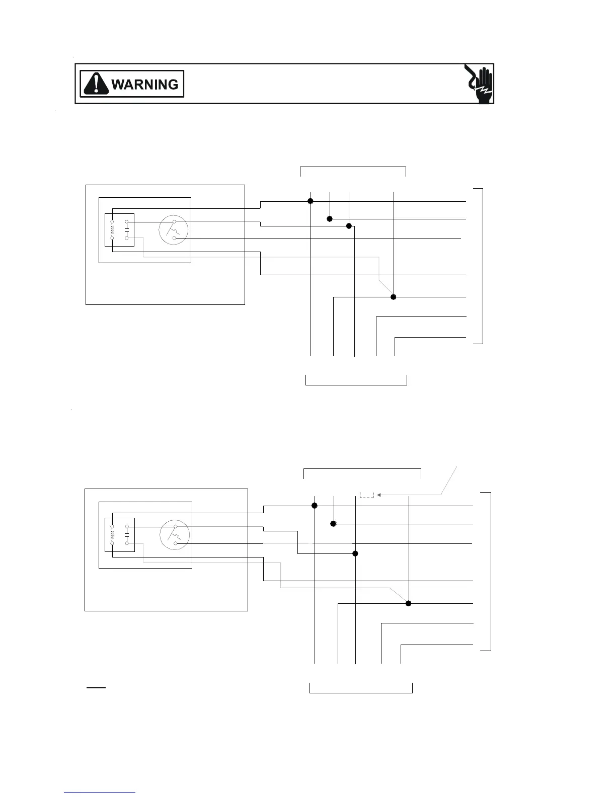
ACCESSORIES WIRING DIAGRAMS
HIGH VOLTAGE!
DISCONNECT ALL POWER BEFORE SERVICING OR INSTALLING THIS
UNIT. MULTIPLE POWER SOURCES MAY BE PRESENT. FAILURE TO
DO SO MAY CAUSE PROPERTY DAMAGE, PERSONAL INJURY OR DEATH.
EMERGENCY
HEAT
RELAY
13
42
BLUE
WHITE
BLACK
BROWN
THERMOSTAT
OT/EHR18-60
21
From Air Handler
CGW2 R
CRW2OY
From Outdoor Unit
C
G
W2
E
R
O
Y
Indoor Thermostat
B
LU
E
GR
E
EN
W
HITE
R
ED
BL
U
E
R
E
D
WHI
T
E
ORANGE
Y
EL
L
O
W
10kw and Below, One Stage Electric Heat
RED
EMERGENCY
HEAT
RELAY
1
42
BLUE
WHITE
BLACK
BROWN
THERMOSTAT
OT/EHR18-60
21
From Air Handler
CGW2 R
CRW2OY
From Outdoor Unit
C
G
W2
E
R
O
Y
Indoor Thermostat
W3
BLUE
GREEN
WH
I
TE
RED
B
R
OWN
B
L
U
E
R
E
D
W
HIT
E
OR
A
N
G
E
YE
L
LOW
15kw and Above, Two Stage Electric Heat
3
RED
SEE NOTE
Note:
When using a Thermostat with only one
stage for electric heat (W2), tie white and
brown wires from air handler together.
Typical Wiring Schematics for OT/EHR18-60 (Outdoor Thermostat & Emergency Heat Relay).
This wiring diagram is for reference only. Not all wiring is as shown above.
Refer to the appropriate wiring diagram for the unit being serviced.
 Loading...