Published 08-25-09, Control # 077-04 2-85
RT9130E SERVICE MANUAL HYDRAULIC SYSTEM
Assembly
NOTE: Lubricate seals and rings with clean hydraulic oil.
NOTE: Make sure the gaps of the two wear rings are 180
degrees apart.
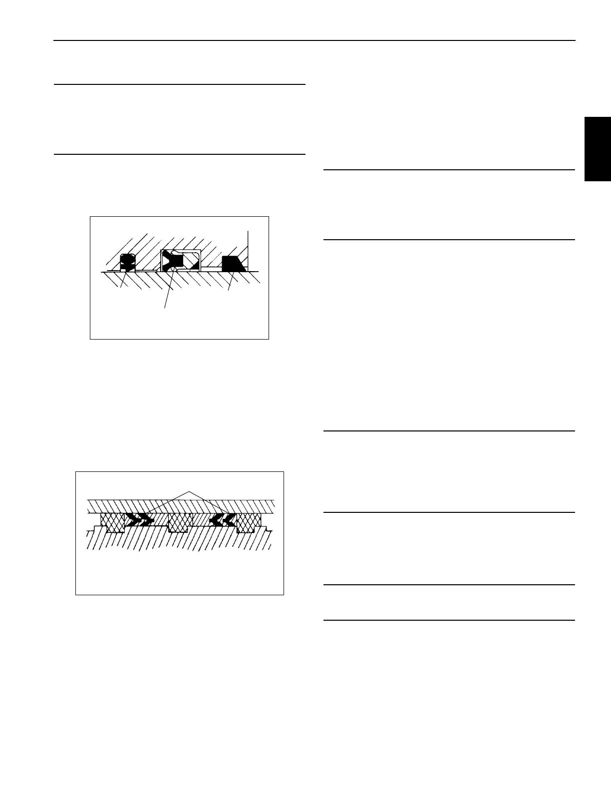
1. Install the replacement wear rings, buffer seal, rod seal
and wiper ring in the inside of the head (Figure 2-48).
Make sure the buffer seal’s step is away from the wear
rings. Make sure the deep Z rod seal rim groove is closer
to the wear rings.
2. Install the replacement o-ring and the backup ring on the
outside of the head.
3. Install the replacement o-ring and backup rings in the
inside of the piston.
4. Install one replacement hydrolock seal on the outside of
the piston (Figure 2-49). Leave the other hydrolock seal
off for now so there is still access to the piston’s set
screw hole.
5. Lubricate the rod with clean hydraulic oil.
6. Slide the head, larger OD end first, onto the rod.
7. Slide the spacer onto the rod.
8. Screw the piston onto the rod until it can go no farther.
Hold the piston in place with the set screw.
9. Install the other replacement hydrolock seal on the
outside of the piston over the set screw. Make sure the
“vees” on the two hydrolock seals point at each other.
10. Lubricate all parts freely with clean hydraulic oil.
11. Remove the cover from the barrel. Insert the rod and
attached parts into the barrel with a slight twisting
motion.
12. Clean all oil from the threads of the head. Coat the
threads with an anti-seize compound (Never-Seez paste
lubricant or similar lubricant). Using a chain wrench,
screw the head into place on the barrel so its larger OD
end is flush with the end of the barrel.
13. Check the inside of the port block for any sharp edges or
burrs and remove as necessary with emery cloth.
14. Install new o-rings onto the check valve.
15. Lubricate the check valve and o-rings with clean
hydraulic oil.
NOTE: The check valve should turn by hand until
compression of the o-rings begins.
16. Carefully install the check valve into the port block until
fully seated.
17. Pressurize and cycle the cylinder with hydraulic oil
pressure. Test the cylinder at 3620 kPa (5250 psi).
Check for proper operation and any leakage. Make
repairs as needed.
CAUTION
When installing new seals and rings, avoid stretching
seals or scratching the grooved or gland surfaces. Make
sure parts are clean before and during assembly. Make
sure seals and rings are installed in the proper order.
Wiper Ring
Deep Z Rod Seal
Buffer Seal
FIGURE 2-48
Hydrolock Piston Seals
FIGURE 2-49
CAUTION
Exercise extreme care when handling the rod. Damage to
the rod surface may cause unnecessary maintenance
and expense. Also, take care to avoid damaging grooved
or gland surfaces or rings or seals during rod insertion.
CAUTION
Do not damage the o-rings during installation of the check
valve. If the check valve turns freely then gets hard to turn,
then easy to turn, remove the check valve and check the
o-rings. They have probably been damaged by a sharp
edge of a port.
CAUTION
Do not use air pressure to cycle or pressurize the cylinder.