Page 33
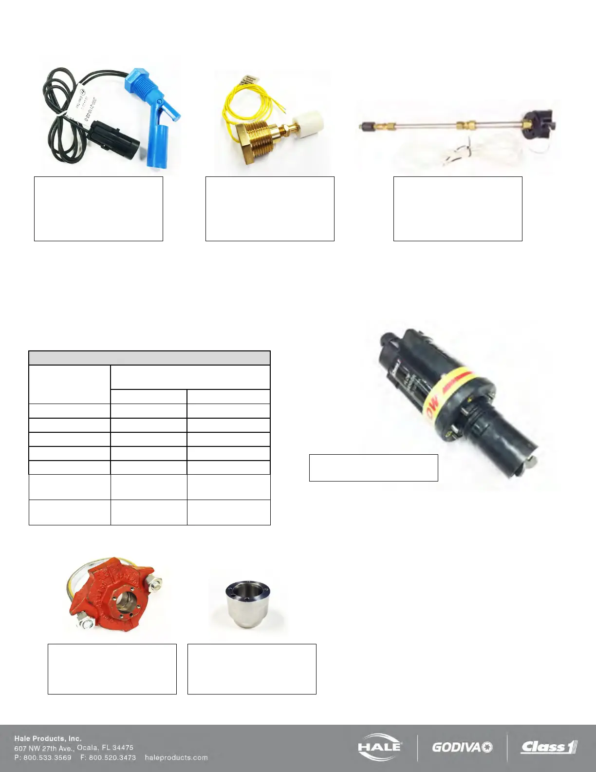
LOW TANK SENSOR OPTIONS
FLOW SENSOR OPTIONS
Each Hale foam system requires a flow sensor for operation. Pipe size must be selected based on the minimum and maxi-
mum water flow in the foam capable discharge. Following is a list of pipe size and rated flow ranges, along with flow sensor
saddle clamp part number. In all instances, a weld fitting may be substituted for the saddle clamp.
Table 5: Pipe Size Versus Flow Range
Pipe size
Flow Range
1.5”
2.5”
3” Single Check
Valve (SCV)
30 - 750 114 – 2,839
(DCV)
30 - 750 114 – 2,839
Side mount (1/2 inch NPT)
200-2110-02-0
½ inch NPT threaded bushing to
mount from outside foam tank.
Bottom mount (1 inch NPT)
200-2100-04-0
1 inch NPT threaded bushing to
mount from outside foam tank
200-2110-06-0
Extends from 2.5 feet to 5 feet –
may be cut shorter if required.
Stainless steel – 082-3060-00-0
Steel – 309020
Aluminum - 309010
2.0 inch – 4842010
2.5 inch – 4843010
3.0 inch – 4844010
102714