Page 51
IN-LINE STRAINER VALVE
CAUTION!
THE IN-LINE STRAINER/VALVE ASSEMBLY, MOUNTED ON THE FOAM PUMP INLET, IS A LOW PRESSURE DE-
VICE. IT CANNOT WITHSTAND FLUSHING WATER PRESSURE. WHEN INSTALLING THE IN-LINE STRAINER
EQUIPPED WITH HALE MDT II OR MST, MAKE SURE THE IN-LINE STRAINER/VALVE ASSEMBLY IS IN THE HOSE
ON THE INLET SIDE OF THE VALVE. IF THE STRAINER IS SUBJECT TO FLUSHING WATER PRESSURE, USE
HALE FS SERIES STRAINERS.
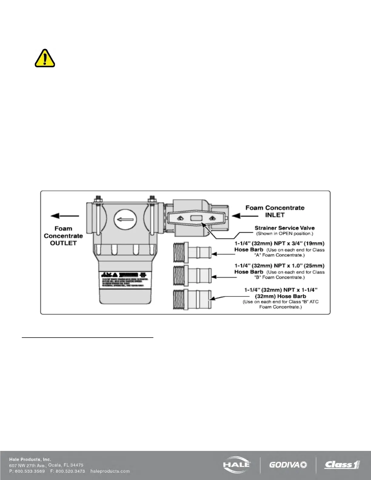
The strainer/valve assembly has 1-1/4” (32 mm) NPT female threaded ports. Fittings are supplied for connection to the
following inside diameter hose, depending on the viscosity of foam concentrates used (Figure 33).
❑ 3/4” (19 mm)
❑ 1.00” (25 mm)
❑ 1-1/4” (32 mm)
Use 3/4” (19 mm) inside diameter hose for Class “A” foam and a 1.00” (25 mm) inside diameter hose for Class “B” foams.
For high viscosity Class “B” foam concentrates use 1-1/4” (32 mm) or 1-1/2-in (38 mm) inside diameter hose (Figure 33).
A bracket is included to permit installation on the apparatus.
Figure 33: In-Line Strainer/Valve Installation
To Install the In-Line Strainer/Valve Assembly
1. Choose a location on the apparatus that allows gravity feed from the foam tank to the strainer inlet and from the
strainer outlet to the foam pump suction connection.
Notes: When selecting the strainer location, make sure there is sufficient space above and below the strainer.
❑ A minimum of 5” (127 mm) below for removal of the strainer basket and screen for cleaning
❑ 2” (51 mm) above to permit operation of the service valve
2.
Mark 4 holes to mount the foam strainer bracket. Drill tapped holes for 1/4”-20 UNC screws (#7 drill for
¼-20 UNC tap)...or...drill clearance holes for 9/32” (7 mm) for 1/4”-20 UNC screws. (Refer to
Figure 34.)