Page 49
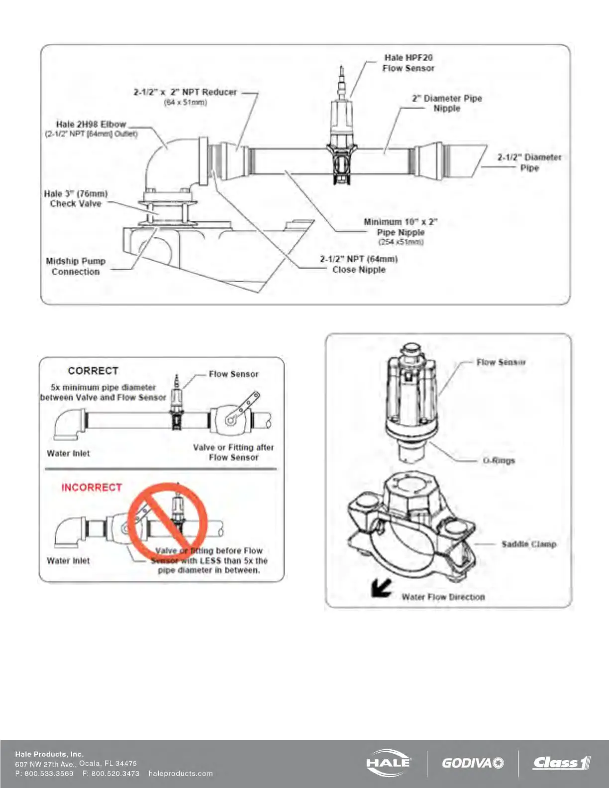
Figure 30: Typical Reduced Size Sensor Piping Arrangement
Figure 31: Flow Sensor Placement
SADDLE CLAMP INSTALLATION
Installation of the paddlewheel flow sensor using a sad-
dle clamp requires a 1.385/1.390 inch (35/35.3 mm)
bored hole in the pipe (Figure 32).
A minimum of six times the pipe diameter of straight run
pipe without any fittings is necessary prior to the position
of this hole.
Figure 32: Flow Sensor/Saddle Clamp Installation
The flow sensor requires a spacer and eight stainless
steel internal hex head screws. These are supplied with
the sensor.
Four 6-32 x1/2 inch screws attach the spacer to the sad-
dle clamp mount and four 6-32 x 3/4 inch screws with
lock washers attach the paddlewheel to the spacer.