Page 54
CHECK VALVE / INJECTOR FITTING
The Hale check valve/injector fitting, supplied with the
Hale SmartFOAM system, meets NFPA requirements for
a non-return device in the foam injection system. It pre-
vents back flow of water into the foam concentrate tank.
When properly installed the brass and stainless steel
construction check valve/injector fitting ensures foam
concentrate is injected into the center of the water flow
for better mixing.
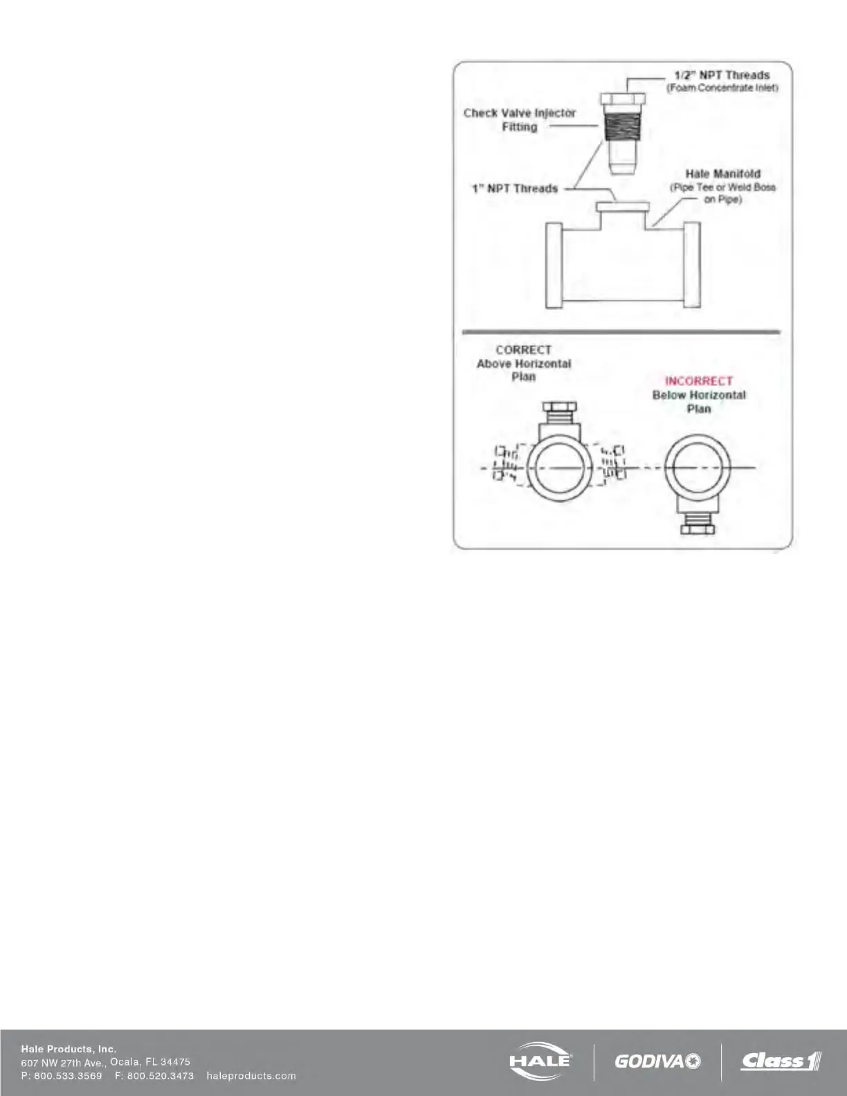
Note: Always position the check valve/ injector fitting at
a horizontal or higher angle to allow water to drain away
from the fitting (Figure 37). This avoids sediment de-
posits or the formation of an ice plug.
The check valve/injector fitting MUST be mounted in a
location that is common to all discharges which require
foam concentrate (Figure 38).
The Hale SmartFOAM system DOES NOT permit a sep-
arate injection point for each foam capable discharge.
However, when running Dual Pump (2) mode, the 2 in-
jection points must be installed on separate manifolds
since the pumps are designed to function independently.
The check valve/injector fitting has – 1” NPT (25.4 mm)
threads on the outside, to fit into the 1” NPT threaded
connection on the Hale mini manifold a pipe tee, or a 1”
NPT weld fitting installed in the discharge piping of the
fire pump (Figure 37).
The inlet connection of the check valve/ injector fitting
uses a 1/2-in NPT female thread.
Figure 37: Check Valve Injector Fitting Installation