Page 63
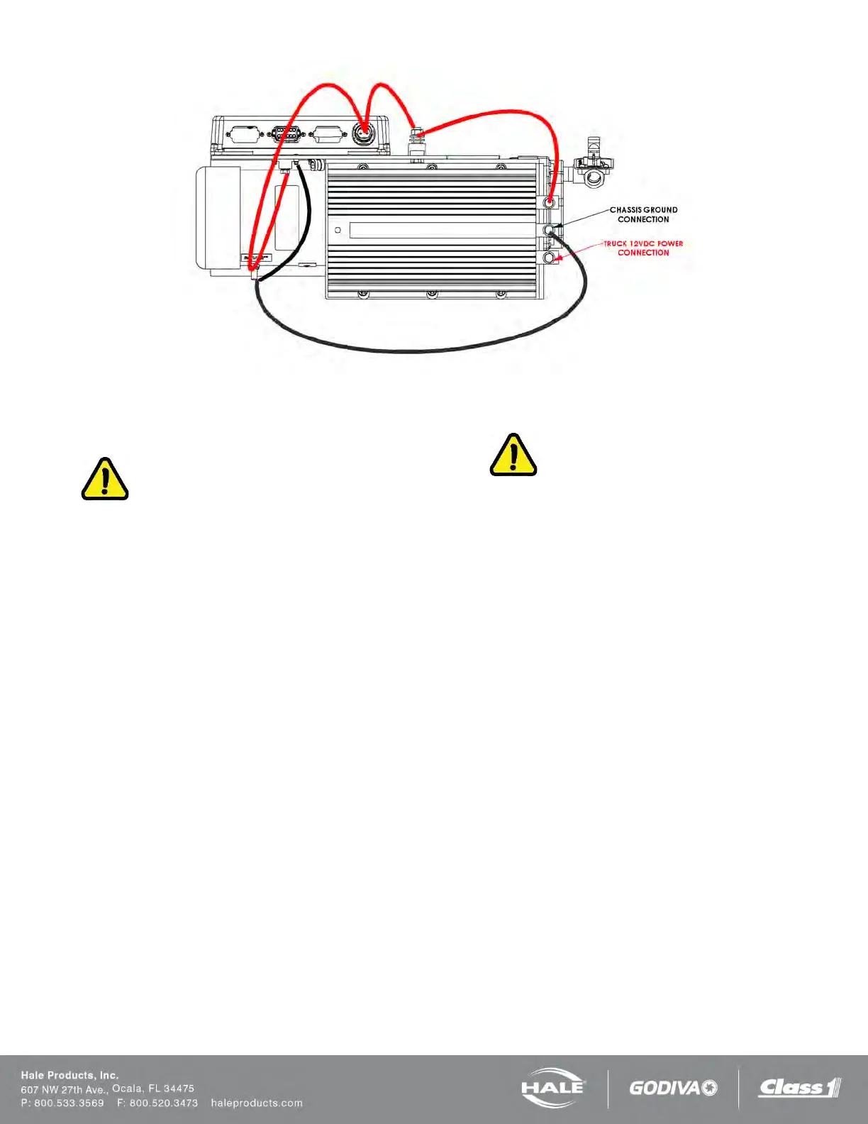
Figure 50: SmartFOAM Power and Ground Connections (6.5 12VDC)
MOTOR GROUND / PRIMARY POWER
CAUTION!
CONNECT THE PRIMARY POSITIVE LEAD FROM
THE TERMINAL BLOCK TO THE MASTER SWITCH
TERMINAL OR RELAY TERMINAL USING AWG TYPE
SGX (SAE J1127), CHEMICAL RESISTANT,
BATTERY
CABLE PER Table 6 OF THIS MANUAL AND PRO-
TECT WITH WIRE LOOM.
PREVENT CORROSION OF POWER AND GROUND
CONNECTIONS BY SEALING THESE
CONNECTIONS
WITH THE SILICONE SEALANT PROVIDED.
GROUND CONNECTION
Be sure the Hale SmartFOAM system is grounded to
the
chassis. Use a short length of wide flat ground strap at
least 1-1/4” (32 mm) wide and less than 18” (457 mm)
long to reduce the potential of RFI emitted by this con-
nection.
A stud is located on the mounting base to attach the
chassis ground strap to the Hale SmartFOAM system
(Figure 48, Figure 49, or Figure 50).
When making the ground strap connections make sure
lugs are soldered to the strap ends for trouble free con-
nections. Seal all connection against corrosion.
When the length of the ground strap exceeds 18” (457
mm) use a wider strap or a double thick strap.
CAUTION!
DO NOT CONNECT THE MAIN POWER LEAD TO
SMALL LEADS THAT ARE SUPPLYING SOME OTHER
DEVICE, SUCH AS A LIGHT BAR OR SIREN, AS THE
SMARTFOAM SYSTEMS HAVE A LARGE CURRENT
DRAW.
PRIMARY POWER SUPPLY CONNECTION
Ensure adequate switched electrical power from the bat-
tery positive (+) terminal to the “IN” connection stud on
the motor controller is provided (Table 6: Recom-
mended Primary Power Cable Sizes).
Use type SGX (SAE J1127) battery cable directly to the
battery, battery switch or solenoid. DO NOT
connect
power to the same connection as the pump primer.
When connecting the 12 V 6.5 system with the converter
located remote, wire the converter input and converter out-
put using Table 6: Recommended Primary Power Ca-
ble Sizes.
RFI / EMI
Proper installation of system components and cables
along with proper grounding will limit radio interference
caused by the Hale SmartFOAM system. Additionally,
make sure radio cables and hardware are not located in
the immediate area where Hale SmartFOAM equipment
is mounted.
Making round coils of extra control and flow sensor ca-
bles in the pump compartment can act as an antenna.
While the control and flow sensor cables cannot be
shortened, various lengths of cable are available to mini-
mize the “extra” cable in the truck.