Page 70
CAUTION!
USE THE SILICONE SEALER PROVIDED TO INSULATE AND PREVENT CORROSION.
A connector kit (Hale p/n: 546-1780-00-0) is available that contains a Packard WeatherPack 2-contact shroud half, two (2)
14-16 gauge male terminals and two (2) 14-16 gauge cable seals. Assemble these components to the end of the low tank
sensor wires.
Snap the two halves of the WeatherPack connector together making sure they are sealed.
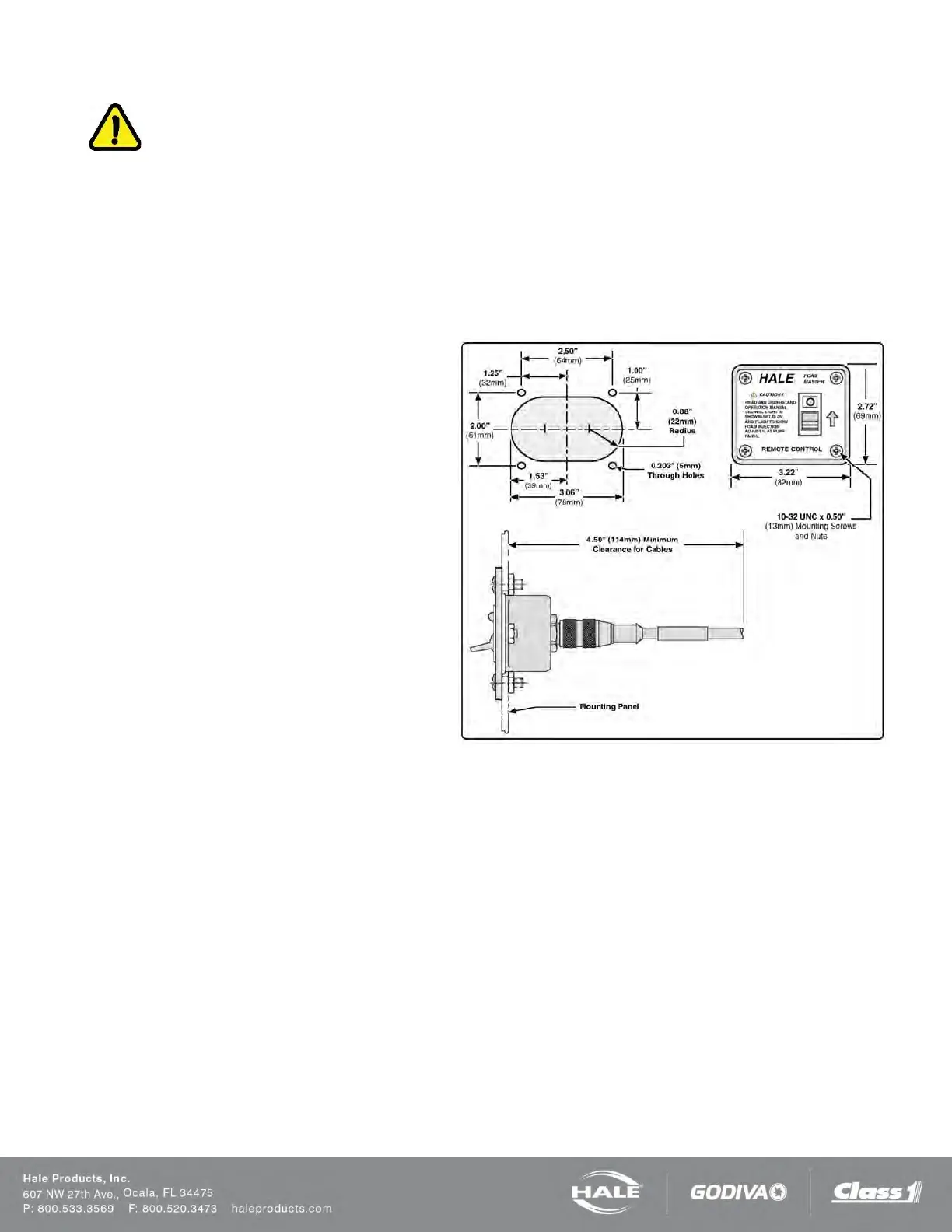
REMOTE ACTIVATION SWITCH OPTION
Choose a location in the apparatus personnel com-
partment for mounting the remote activation switch.
Make sure the switch is accessible to the operator
without interfering with other controls on the appa-
ratus.
Install the remote activation switch as follows:
1. Cutout the panel and drill the four 0.203 inch
(5 mm) diameter through holes (see Figure 48: Re-
mote Activation Switch Installation Dimensions).
2. Insert switch assembly through the panel cutout
and secure to using the #10-24 UNC x 1/2-in (13 mm)
screws and nuts provided.
Note: When making cable connections, make sure the
cable is routed by the shortest most direct route. A
maximum of 40 feet (12 meters) of remote cable may
be used.
3. Connect the remote activation switch cable from the
main cable harness connector C2 (Figure 45 or Fig-
ure 46).
Figure 56: Remote Activation Switch Installation Dimen-
sions