Page 41
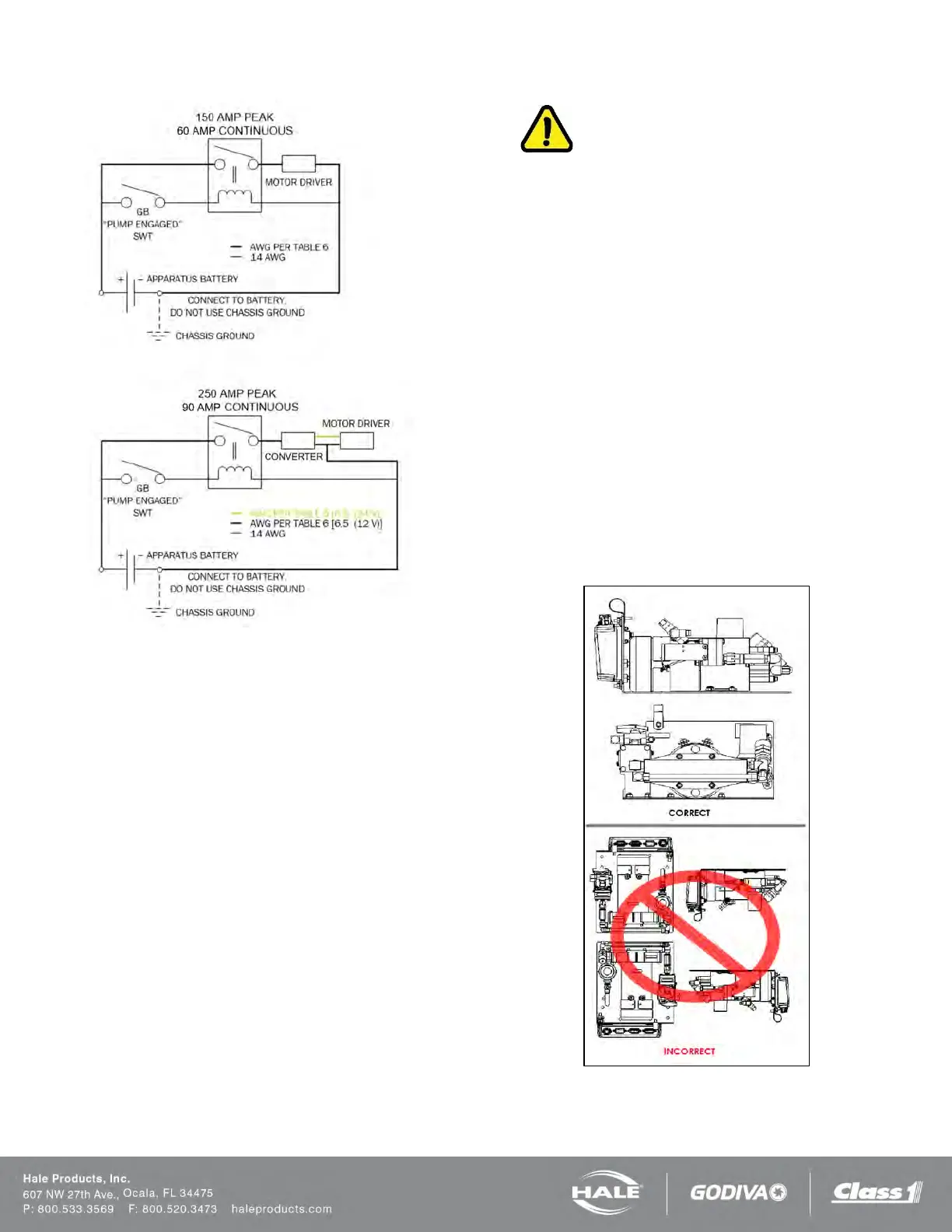
Figure 20: Recommended Relay Wiring Schematic
TOP = All Except 6.5 (12VDC) System,
BOTTOM = 6.5 (12VDC) System Only
When planning cable runs make sure the primary wires
are routed by the shortest most direct route. Use Table 6,
24V max lengths between a remoted converter and the
pump/motor.
A braided flat ground strap connected to the apparatus
chassis is recommended for the ground connection.
This limits the RFI/EMI interference encountered with ra-
dios, computers or other sensitive electronic equipment.
The ground strap should be a minimum of 1-1/4-in
(32 mm) wide and no longer than 18-in (457 mm). It must
have soldered flat lug ends with 3/8-in (10 mm) diameter
holes. If the ground strap length exceeds 18-in (457 mm),
a wider ground strap should be used or use a double thick-
ness of 1-1/4-in (32 mm) wide ground strap. The ground
strap must be connected to the chassis. Use minimum
5/16-in (8 mm) diameter bolt or mounting to secure the
strap.
Power and ground must also be provided for the display
unit using the 2 pin Packard connector. The power must
be a minimum 5 amp dedicated and fused circuit. The
ground must be connected to the chassis ground stud and
protected from corrosion. Make sure the ground is at-
tached directly to the chassis frame and not to the appa-
ratus body work.
IMPORTANT!
BEFORE MAKING GROUND CONNECTIONS REMOVE
ALL PAINT, GREASE AND COATINGS FROM THE CON-
NECTION AREA. AFTER MAKING CONNECTION, SEAL
AGAINST CORROSION. WHEN A FLAT GROUND STRAP
IS NOT AVAILABLE USE A BATTERY CABLE ONE SIZE
LARGER THAN THE POWER CABLE USED.
FOAM CONCENTRATE TANK
A foam concentrate tank must be supplied to suit the capac-
ity required for the apparatus application. The tank must
meet NFPA minimum standards for its design capacity, in-
cluding:
❑ Filler size
❑ Vapor pressure venting
❑ Baffling
❑ Drain facilities
FOAM PUMP MOUNTING
Position the foam pump and motor assembly in the desired
location on the apparatus. When installing the foam pump
and motor assembly, the assembly should be kept in a
HORIZONTAL position with the base plate on the bottom.
(See Figure 21 or Figure 22).
Figure 21: SmartFOAM Piston Pump Installation