Page 42
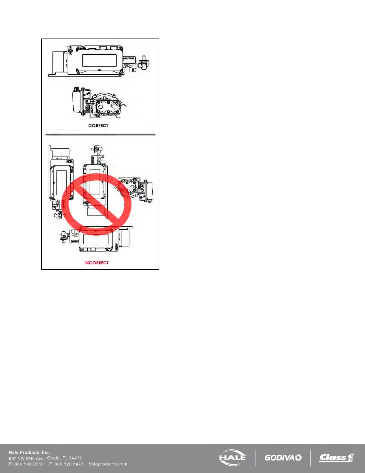
Figure 22: SmartFOAM Gear Pump Installation
Although the system is sealed and designed to be resistant
to the harsh environment of fire-fighting apparatus, a com-
partment with easy operator access is recommended.
The base plate of the foam pump and motor assembly must
be anchored to a surface or structure that is rigid and of ade-
quate strength to withstand the vibration and stresses of ap-
paratus operation.
The base of the foam pump and motor assembly includes
5/16” (8 mm) diameter predrilled mounting holes. The appa-
ratus mounting location must to be drilled accordingly. The
base plate may be used as a template to mark mounting
hole locations.
Figure 23 provides the mounting base dimensions for the
SmartFOAM 1.7AHP and 2.1A foam pump and motor as-
sembly.
Figure 24 provides the mounting base dimensions for the
SmartFOAM 3.3, 5.0, and 6.5 foam pump and motor assem-
bly.
Figure 25 provides the mounting dimensions for the con-
verter for the SmartFOAM 6.5 (12V) system when the con-
verter is mounted separate from the pump and motor as-
sembly.
Make sure the foam concentrate hoses are properly routed
to the inlet and outlet on the foam pump.
Foam concentrate must gravity feed to the foam pump inlet
from the foam tank(s). The foam pump must be mounted in
an area to avoid excessive engine exhaust system heat or
accessory heat build-up.