Page 57
ADT OPTION AIR CONNECTIONS
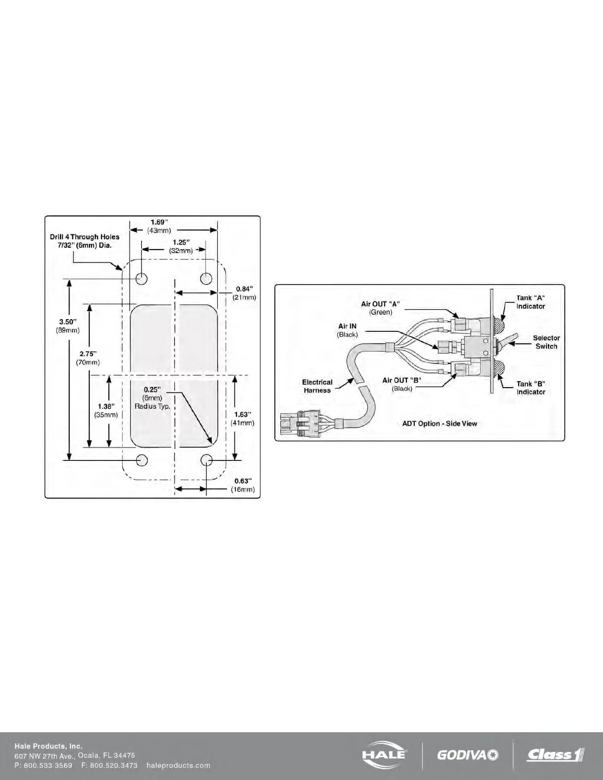
If the ADT option is used, install the operating switch and indicator light placard on the apparatus operator panel. A
mounting cutout diagram is provided (Figure 41).
After mounting the placard assembly install the air hoses from the ADT to the placard assembly. Make sure proper con-
nections are made at the placard assembly (Figure 42).
A color coded decal attached to the ADT valve assembly along with an optional color coded air hose harness simplifies air
hose connections. If the optional air hose harness is not used, 1/4” (6 mm) inside diameter air brake tubing can be substi-
tuted. Make sure the air brake tubing selected has the proper DOT approval (Figure 42 and Figure 43).
When cutting the air harness or air brake tubing to size make sure the ends are square using a tubing cutter or razor
knife.
Figure 41: ADT Option Panel Placard Layout
Dimensions
Figure 42: ADT Air Hose Connection, Part 1