Page 46
When properly mounted, the flow sensor and check
valve/injector fitting are on the side of the manifold and one
of the drain ports is on the bottom. The flow sensor should
point upwards slightly to allow drainage of water and sedi-
ment (Figure 29).
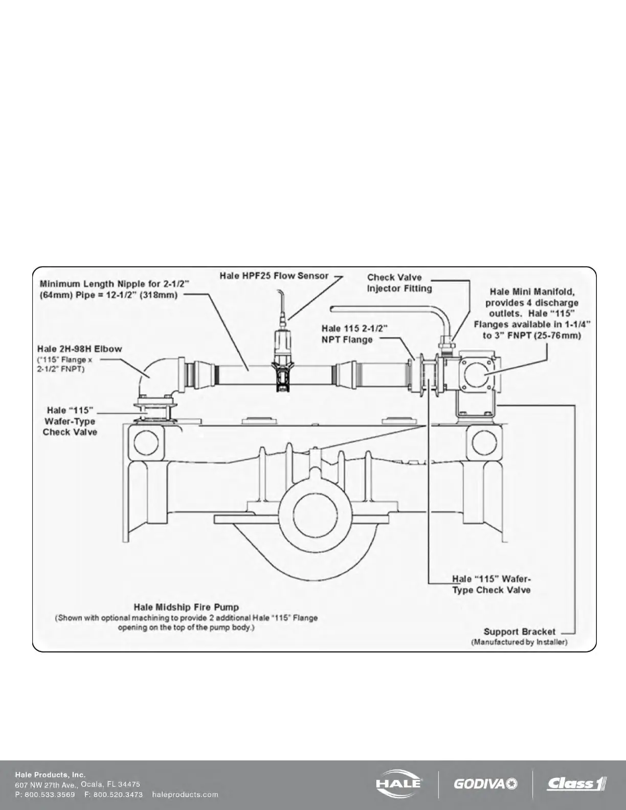
OPTIONAL HALE PIPING COMPONENTS
Hale piping components, such as 3” (76 mm) and 4”
(102 mm) wafer-type check valves, 115 and 2433 series
flanges, mini manifold, etc. are available to simplify installa-
tion of water and foam solution discharge piping.
The arrangement shown in Figure 27 provides accurate
proportioning across a wide range for up to
four discharges
from the mini manifold.
The Hale mini manifold provides a 1” NPT tap for installa-
tion of the check valve/injector fitting.
The Hale mini manifold and elbow components offer 4-3/8”
diameter bolt circles and minimize fabrication and pipe
work. After installation, make sure all pipes, hoses and
tubes are supported using the best industry practices.
Figure 28 shows a suggested installation arrangement us-
ing Hale 4” (102 mm) check valves, pipe and Hale 2433
flanges.
Figure 27: Typical Midship Pump Installation