Page 60
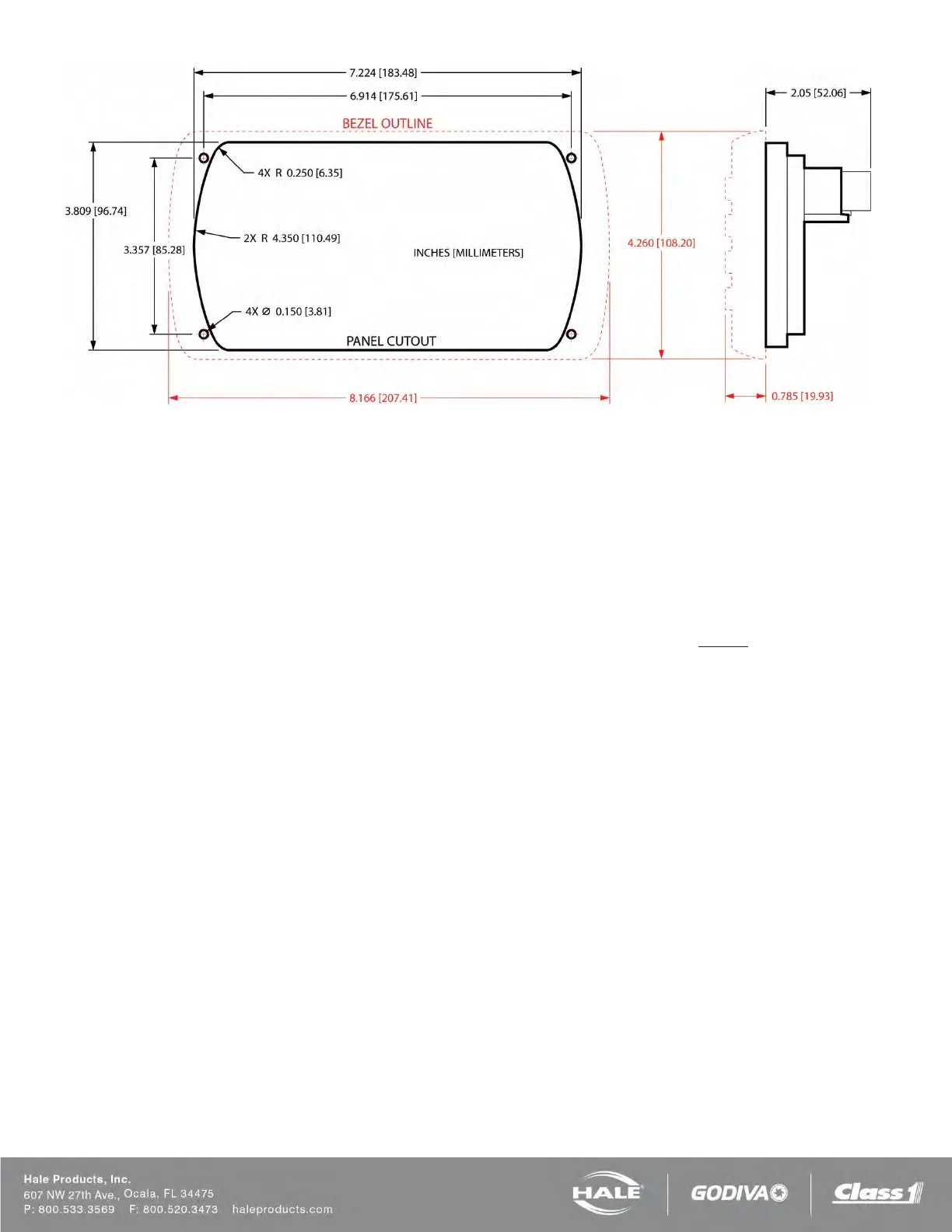
Figure 44: SmartFOAM Controller Unit Mounting Dimensions
CONTROLLER UNIT
The controller unit mounts in the operator panel of
the
apparatus. The display is secured with four #6 pan head
screws and nuts (see Figure 44).
The controller requires a 2.0” (52 mm) minimum clear-
ance from the back of the operator panel to
allow proper
connection of cables.
Single tank models refer to Figure 45 (shown with single
pump harness).
❑ Connect C1 of the controller harness to the “B”
connector on the rear of the controller unit.
❑ Connect C6 of the controller harness to the “C”
connector on the rear of the controller unit.
❑ Connect C13 on the controller harness to C14 of
the pump harness.
❑ Connect C7 of the controller harness to the water
flow sensor input module.
❑ Connect C3 of the controller harness to the water
flow sensor (paddlewheel).
❑ Connect C10 of the pump harness to the low
foam sensor.
❑ C2 and C4 of the controller harness are used for
options (remote start stop and CAN communica-
tion respectively).
❑ C6, C7, C8, C15, and C16 of the pump harness
are pre-connected by Hale Products at the fac-
tory.
Dual tank models refer to Figure 46 (shown with dual
pump harness).
❑ Connect C1 of the controller harness to the “B”
connector on the rear of the controller unit.
❑ Connect C6 of the controller harness to the “C”
connector on the rear of the controller unit.
❑ Connect C13 of the controller harness to C14 of
the (first) pump harness.
❑ Connect C14 of the 513-00074-200 controller
harness to C14 of a second pump harness, as
applicable.
❑ Connect C7 of the controller harness to the water
flow sensor input module.
❑ Connect C3 of the controller harness to the water
flow sensor (paddlewheel).
❑ Connect C8 of the pump harness to the tank A
selector.
❑ Connect C9 of the pump harness to the tank B
selector.
❑ Connect C10 of the pump harness to the tank A
low foam sensor.
❑ Connect C11 of the pump harness to the tank B
low foam sensor.
❑ C2 and C4 of the controller harness are used for
options (remote start stop and CAN communica-
tion respectively).
❑ C6, C7, C15, and C16 of the pump harness are
pre-connected by Hale Products at the factory.
Notes:
Allow a service loop on the controller unit harness con-
nections to prevent “pulling” of the wires or connectors
during body and frame flex.