Page 86
DUAL FOAM PUMP SYSTEMS
There are 2 modes of operation when configured with a dual
foam system. They are referred to as “Dual Pump (1)” and
“Dual Pump (2)”.
DUAL PUMP (1) – DUAL PARALLEL
This mode consists of dual foam pumps used as a single
system with a single SmartFOAM display. It utilizes two of
the same foam pumps (i.e. two 6.5 GPM pumps) in order to
double the amount of foam flow (i.e. 13 GPM) and the two
pumps are utilized in parallel. The display graphics (Figure
71) appear the same as a single pump system (with one wa-
ter flow, one foam percentage, one total foam flow, one total
water flow, and one pump bar graph). These two pumps re-
quired individual injection check valves but can be plumbed
to a single injection point and are controlled from a single
waterflow paddlewheel.
Figure 71: Dual Pump (1) Screen
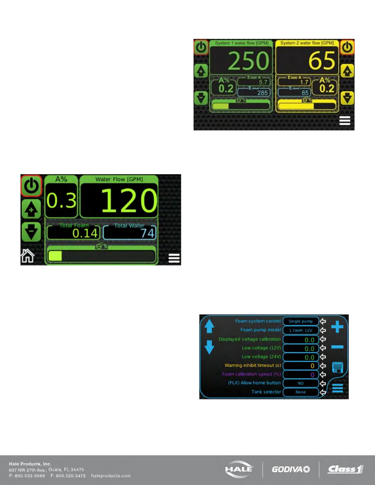
DUAL PUMP (2) – DUAL SERIES
This mode consists of dual foam pumps used as individual
systems with a single SmartFOAM display. This is the mode
required when 2 different sized pumps are needed. It pro-
vides the option of running larger foam flow rates for some
applications (i.e. 3.3 GPM) and then much smaller foam flow
rates for other applications (i.e. 1.7 GPM). The two pumps
are plumbed separately to their own injection check valve
and injection point and they utilize their own separate water-
flow paddlewheels. The graphic on the display (Figure 72)
indicates two separate control systems (with two individual
water flows, two individual foam percentages, two individual
total foam flows, two individual total water flows, and two in-
dividual pump bar graphs).
Figure 72: Dual Pump (2) Screen
DUAL FOAM PUMP TANK SELECTOR
Both MST and MDT II tank selectors can be used on dual
pump systems. Refer to system diagrams for complete sug-
gested plumbing layouts.
1. Dual Pump (1) systems would require 1 of either
MST or MDT II selector since the pumps are to be
running as a single system.
2. Dual Pump (2) systems would require 2 of either
MST or MDT II selector since the pumps are to be
running as separate systems.
3. ADT selector are currently NOT available for either
dual pump (1) or dual pump (2) systems.
CONTROL DISPLAY SETUP
Enter the password “2314” to enter the OEM Menu Screen.
The “Foam System Control” within the OEM Menu screen
needs to be set accordingly depending on system being run.
It is default set as “single pump” from factory. The other
available options are Dual Parallel [Dual Pump (1)] and Dual
Series [Dual Pump (2)].
Figure 73: OEM Menu Screen
FLUSHING THE SMARTFOAM SYSTEM
When returning the apparatus to the ready condition after
foam operations using Class “B” foam, the Hale SmartFOAM
foam pump must be FLUSHED. Some Class “B” foam