Page 56
BYPASS HOSE CONNECTION
Models 1.7AHP and 2.1A
A bypass valve is mounted on the discharge of the foam pump. The bypass handle must be accessible by the pump oper-
ator during normal operations.
The bypass is a 3-way directional valve. Determine which port is the INJECT port and which port is the BYPASS (Figure
38).
Bypass hose connections are 1/2”. Hose fittings compatible with all foam concentrates must be provided. The hose from
the BYPASS port is plumbed to the atmosphere.
This hose is used for calibrating the foam pump, pumping the concentrate into a container to empty the foam tank or to
assist in priming of the foam pump. The hose from the BYPASS port must be long enough to reach a container outside
the truck.
Models 3.3, 5.0, and 6.5
A bypass port is provided on the discharge side of the ADT, or a 1/4 turn bypass valve is mounted on the discharge of the
foam pump when the ADT option is not installed (Figure 40).
The bypass handle must be accessible by the pump operator during normal operations (Figure 39).
The bypass is a 3-way directional valve. Determine which port is the INJECT port and which port is the BYPASS (Figure
40). Bypass hose connections are 1/2-in (13 mm). Hose fittings compatible with all foam concentrates must be provided.
The hose from the BYPASS port is plumbed to the atmosphere and should not receive HIGH pressure.
This hose is used for calibrating the foam pump, pumping the
concentrate into a container to empty the foam tank or to assist in
priming of the foam pump. The hose from the BYPASS port must
be long enough to reach a container outside the truck.
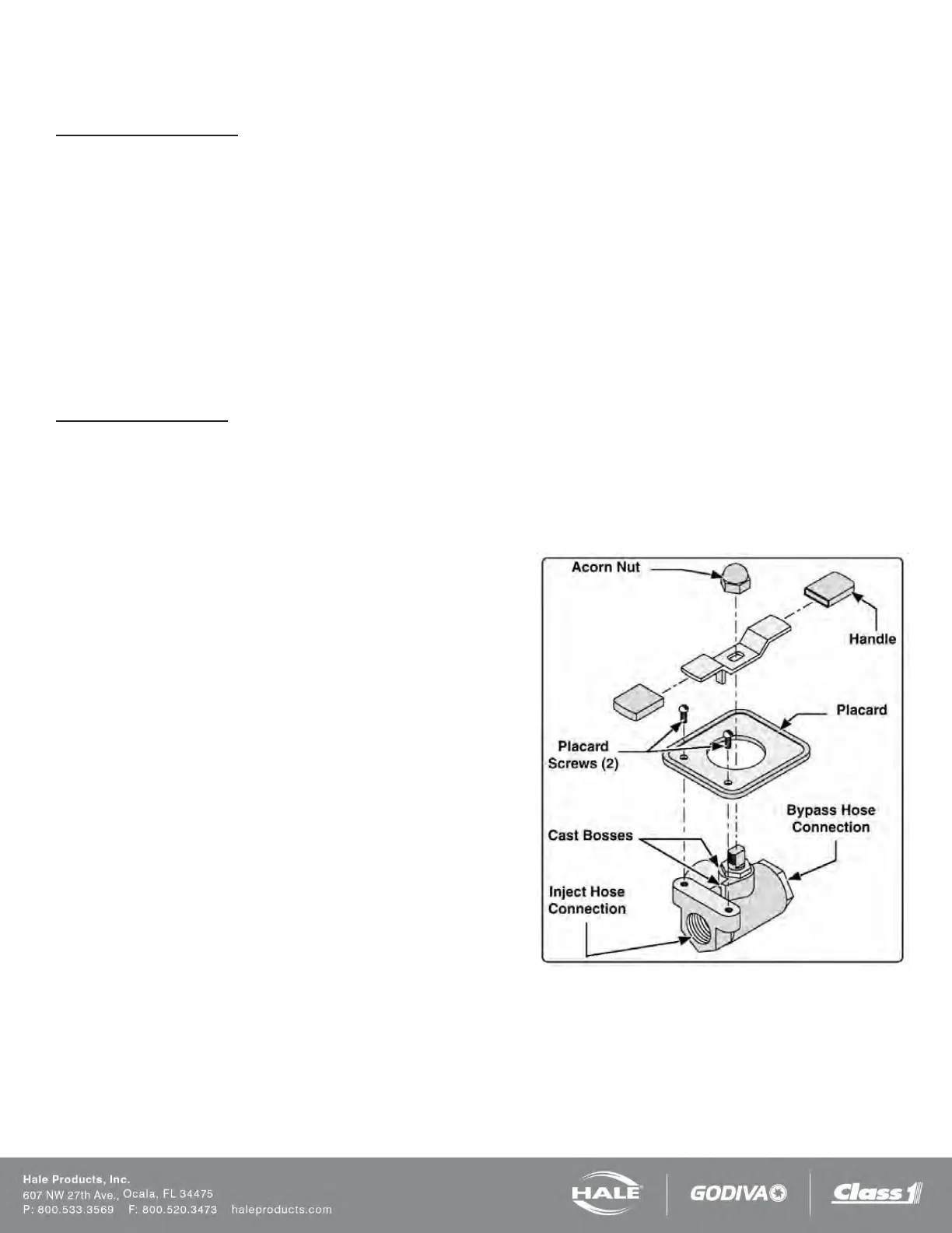
Note: If the handle or placard is removed from the bypass valve
for repairs or to facilitate remote mounting make sure they are in-
stalled on the valve correctly. Make sure the tang on the handle
engages the cast stops (Figure 40).
Figure 40: Bypass Valve Assembly