Page 44
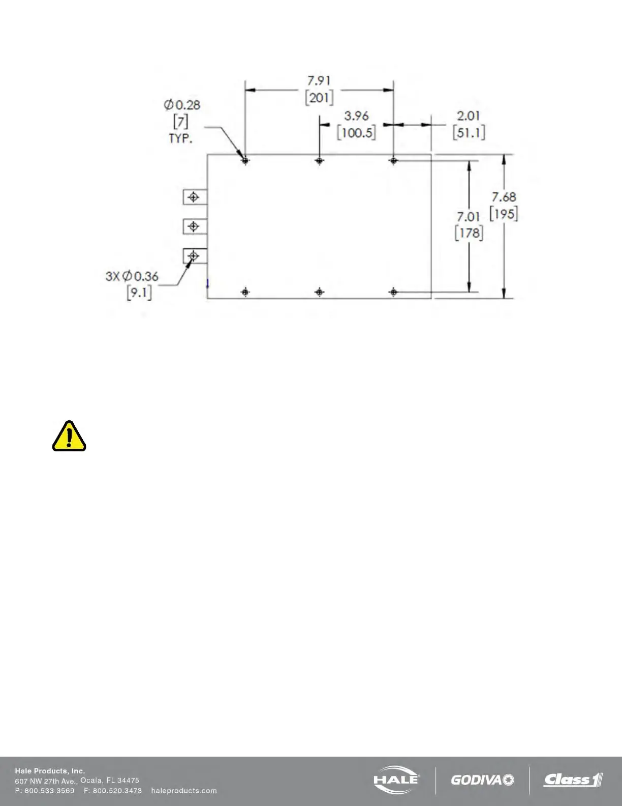
Figure 25: Converter Mounting Hole Locations – 6.5 12VDC (ONLY Required When Installed Remotely)
PLUMBING INSTALLATION
Hale SmartFOAM System plumbing diagram is located below. The diagram provides recommended guidelines for the instal-
lation of system components that handle water, foam concentrate and foam solution. The sequence in which the plumbing
installation is completed depends on your individual installation requirements.
IMPORTANT!
AFTER INSTALLATION, MAKE SURE ALL PIPES, HOSES AND TUBES ARE PROPERLY SUPPORTED USING THE
BEST INDUSTRY PRACTICES. USE A SUITABLE PIPE SEALING COMPOUND AT ALL JOINTS.
WATER AND FOAM SOLUTION PLUMBING
Use best industry practices when installing the water and foam solution piping runs. Use a suitable pipe sealing compound
at all joints.
CHECK VALVE MANIFOLD
Hale pre-made stainless steel foam manifolds are recommended. The manifolds are available in kits and eliminate the extra
labor and leaks from large pipe thread connections. The manifolds use 3” (76 mm) Victaulic connections and are available in
single or dual check valve configurations. Hale currently does not offer a dual injector port manifold. Figure 26 shows a typi-
cal check valve manifold installation.